
This is the journal of my 3D printer experience. I hope it is useful
for you, especially if you build a Kossel kit. If you have questions,
email
I ordered a Kossel (delta-style) 3D printer kit from mixshop.com on Jan 16, 2014. (update 2017/10/04 mixshop appears to have gone under. RIP) They estimated 3 week lead time just to source the parts (they do not keep a big inventory), so I expected at least 6-8 weeks. They also just had a small Kickstarter for their Prusa kits, so I figured they would be a little overloaded and might take even longer. But their price is good, Kossel kits are fairly rare, and I like their business model.
I chose a delta design because the idea of the printbed moving around seems really error-prone to me. Best to have the only moving part be the end effector. Better to have all of the linear actuators symmetrical, too. Also the "Bowden" design that takes the filament extruder off of the end effector seems clever to me, so that the end effector is low mass and can move faster with less stress on the frame.
A note on business models: The tradition in the 3D printer industry (RigidBot, Pirate3d, Makibox, etc) is to attract thousands of customers for a product that doesn't exist yet. Then the assumption is that with so much money, it will be possible to design and mass-produce a printer that is both high quality and low cost. I am sure at least some of these start-ups will succeed and in a few years they will bring an affordable quality printer to the masses. But in the mean time it is hard to try to predict the winner and then wait about a year for delivery.
By comparison, I really like Mixshop's model. Instead of attracting thousands of customers for a hypothetical printer, they are attracting dozens of customers for a kit that they know they can deliver. The downside is that they will have a hard time switching to mass-production in the future. In fact, they are so poorly capitalized that they often don't order parts until after a customer places an order on the website. But the upside is tremendous -- if shipping the first 10 units turns out to be a nightmare, they can sit back and rethink the process. They don't have 1,990 more customers already in line behind those 10, each one complaining about a slipped deadline.
If I start selling my own products, I definitely intend to follow Mixshop's model.
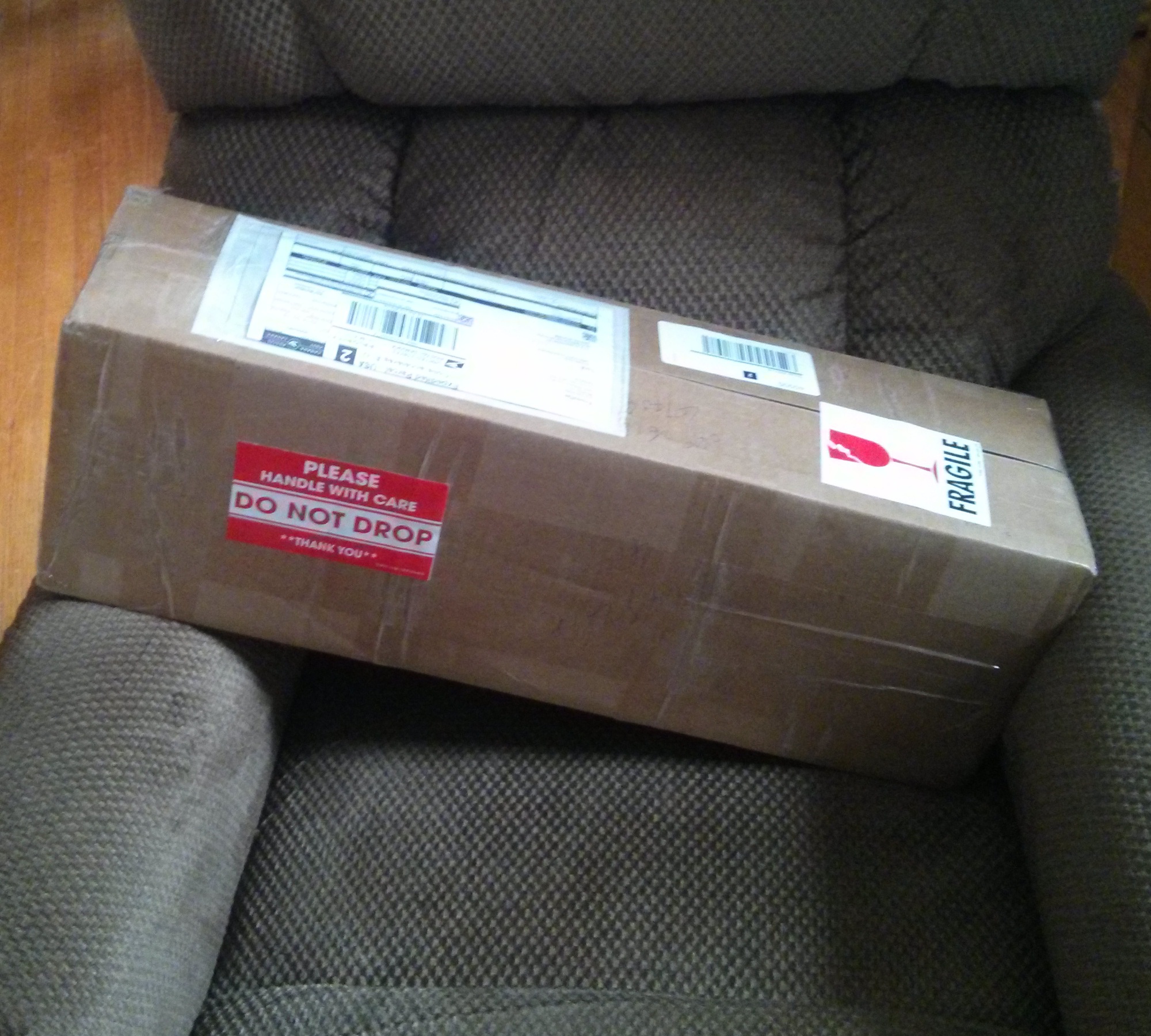
Anyways, they faced delays with their suppliers, which they informed me about and apologized profusely for. They said they would give me a free reel of filament as a consolation. I asked them not to, because small delays don't bother me any. They didn't listen, and shipped the extra filament anyways. So after 9 weeks, the printer arrived! 9 weeks is a little longer than their estimate, but there are people who ordered a printer in 2012 who still haven't received one so I am really impressed by Mixshop!
Anyways, this is the box:
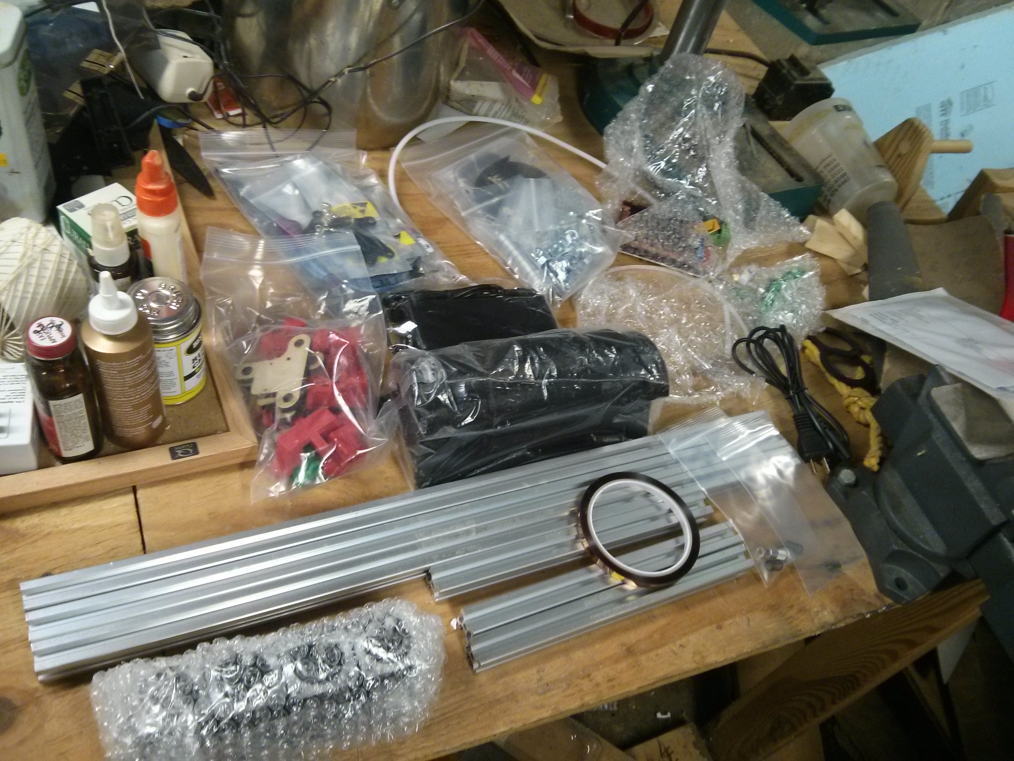
I cleared a space on my workbench (which is still a mess *sigh*), and
unboxed it. The few delicate components (assembled hot end, RAMPS board)
were in bubblewrap in their own box, the rest were all in ziplock bags with
enough foam to keep them from flying around too egregiously.
The first thing I noticed is there is no instruction manual. In hindsight, what was I expecting? Anyways, here are a few resources for it:
Ah! I finally found this on Mixshop's website: Kossel build manuals (and BOM)! Which has a bunch of pictures and matches the kit I actually received much better than those other resources do.
The other thing I noticed is it only has 3 of the short beams, when it should have 9 of them. So I sat down at my computer to write an email to mixshop, and -- this really blew my mind -- they had already sent me an email saying they forgot some parts, and then mailed them to me! They must have stumbled across them when they were inventorying their workshop.
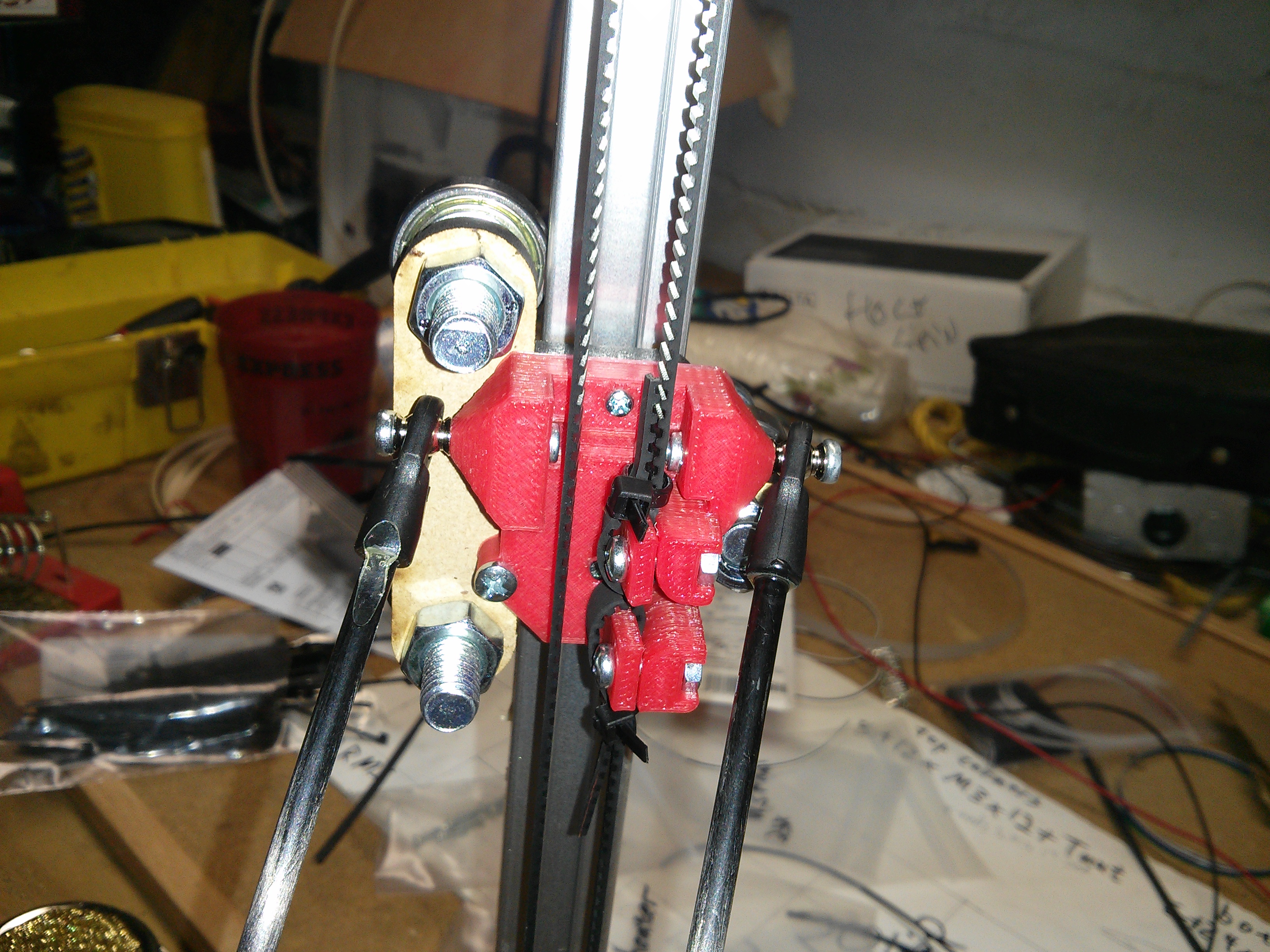
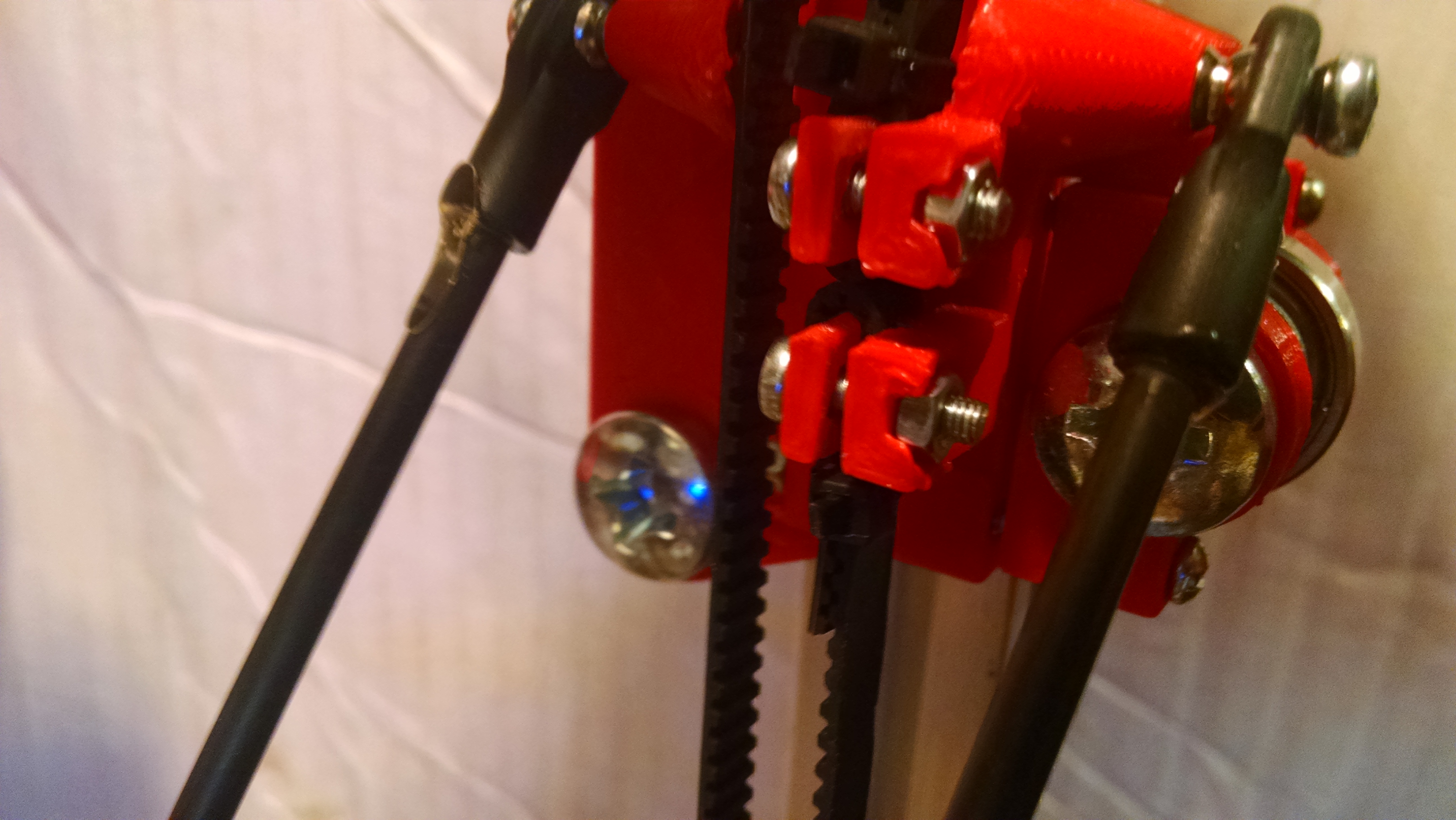
Anyways, it is a good thing I found the Mixshop build manual, because I was starting to think I'd gotten the wrong kit. It turns out they have made a few updates to lower cost. They use common 608 bearings now for the rail carriage, instead of expensive Graber V-rollers. And they seem to be using a little 3D printed pinch connector to attach the PTFE tubing instead of the proprietary "Dupont connectors" -- so I do not need to tap a screw hole for the Dupont connector but I do need to avoid overtightening. And they replaced the flanged bearings at the tensioner pulleys with single 623s, with the printed plastic preventing the belt from slipping off to the side.
Another thing I figured out is I don't think these are Openbeams. I think they are Misumi or 80/20. That's probably why they gave me these fancy T-nuts (which can be inserted into the middle of a beam even if you've already populated it with other nuts). And maybe that's part of why they are able to avoid the expensive V-rollers?
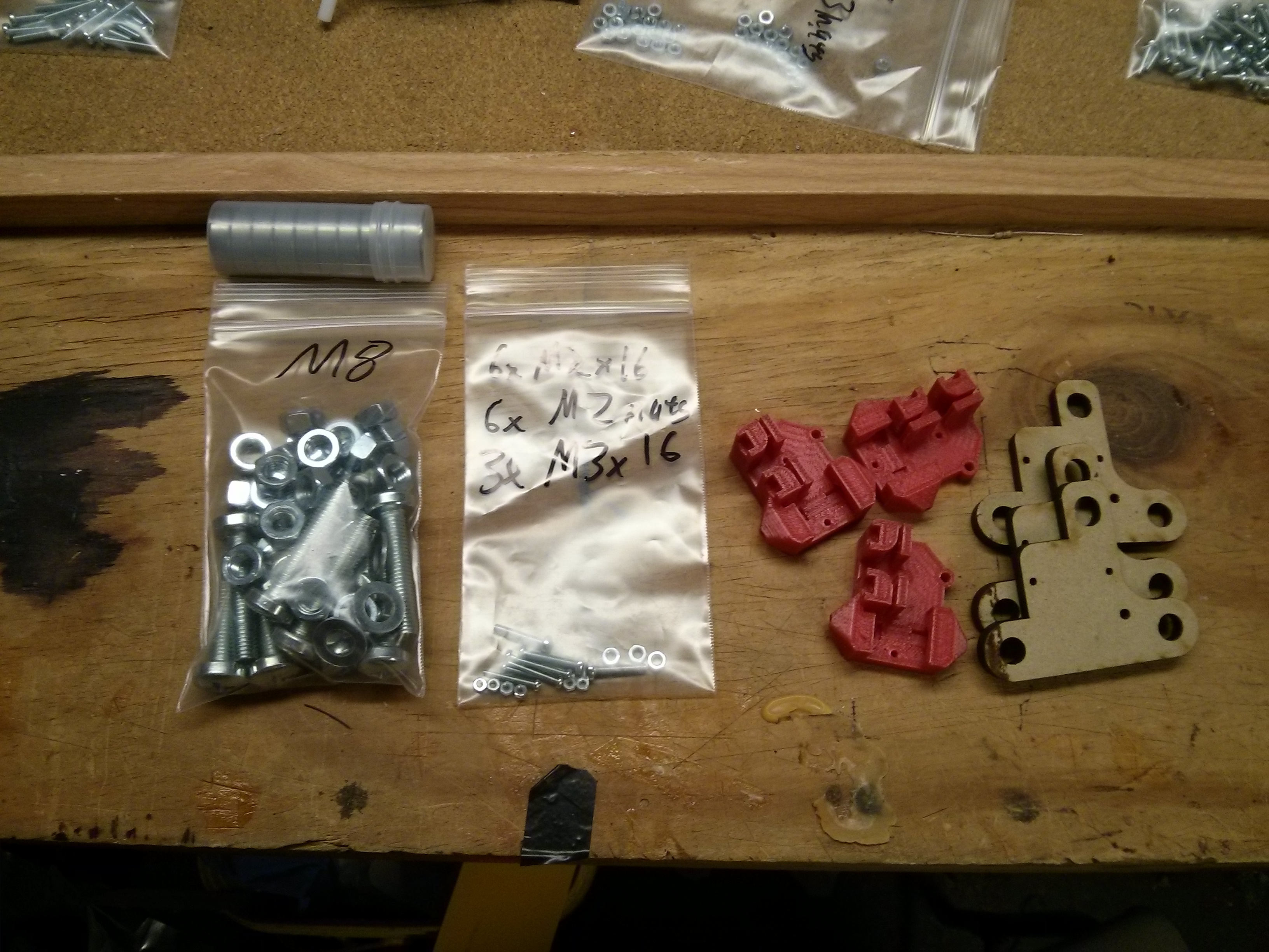
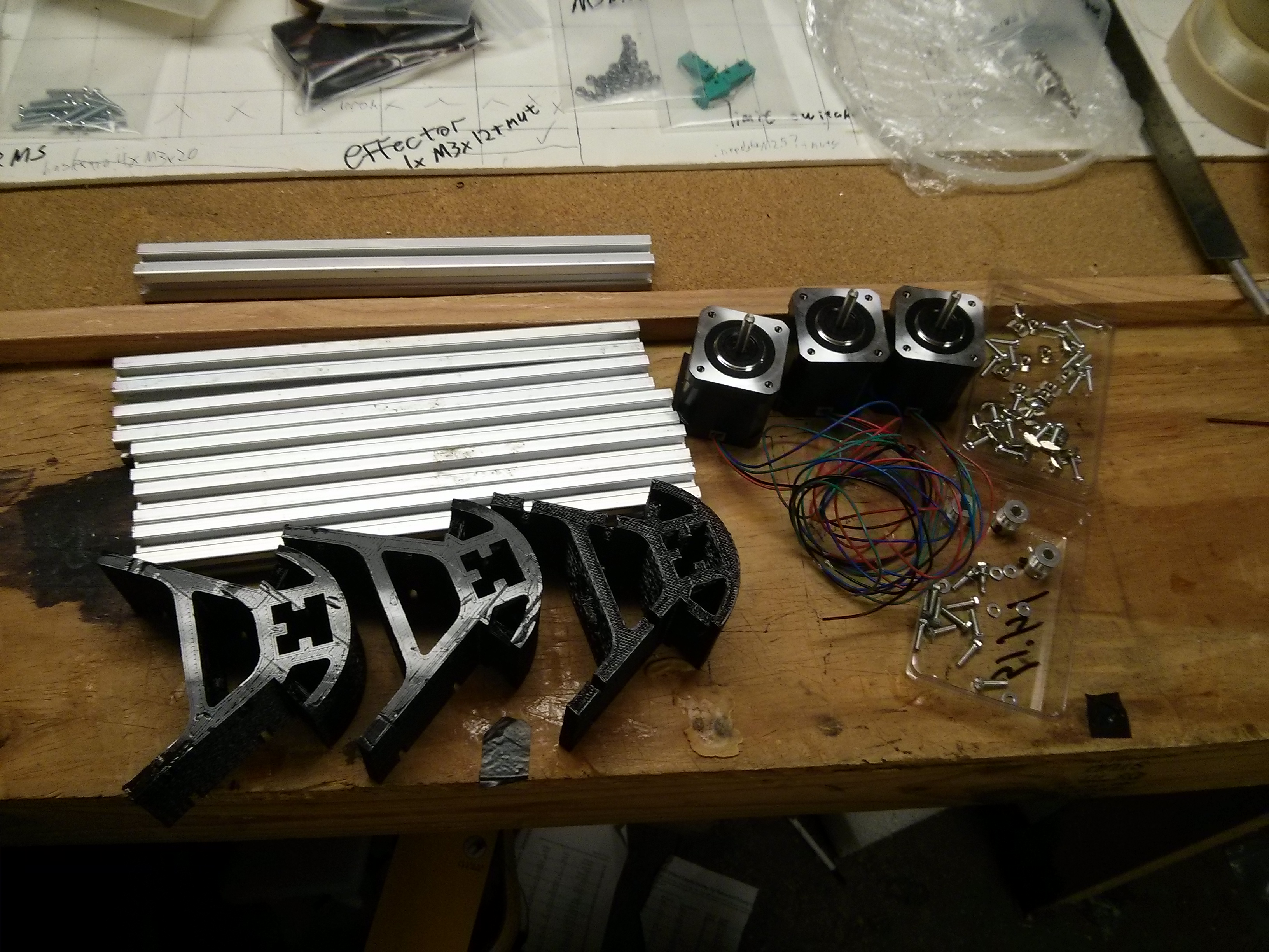
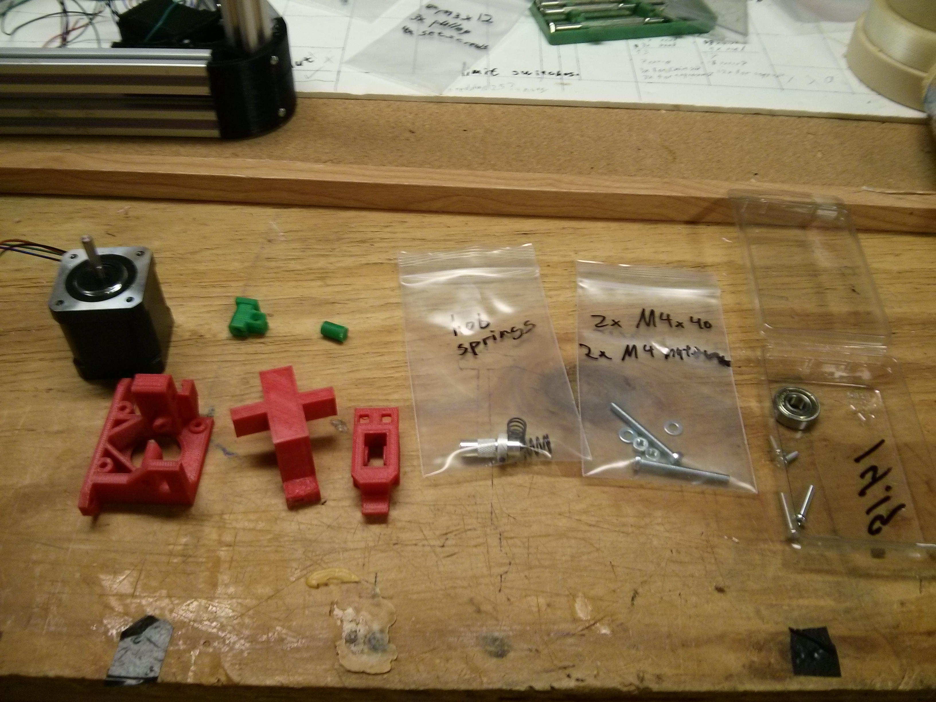
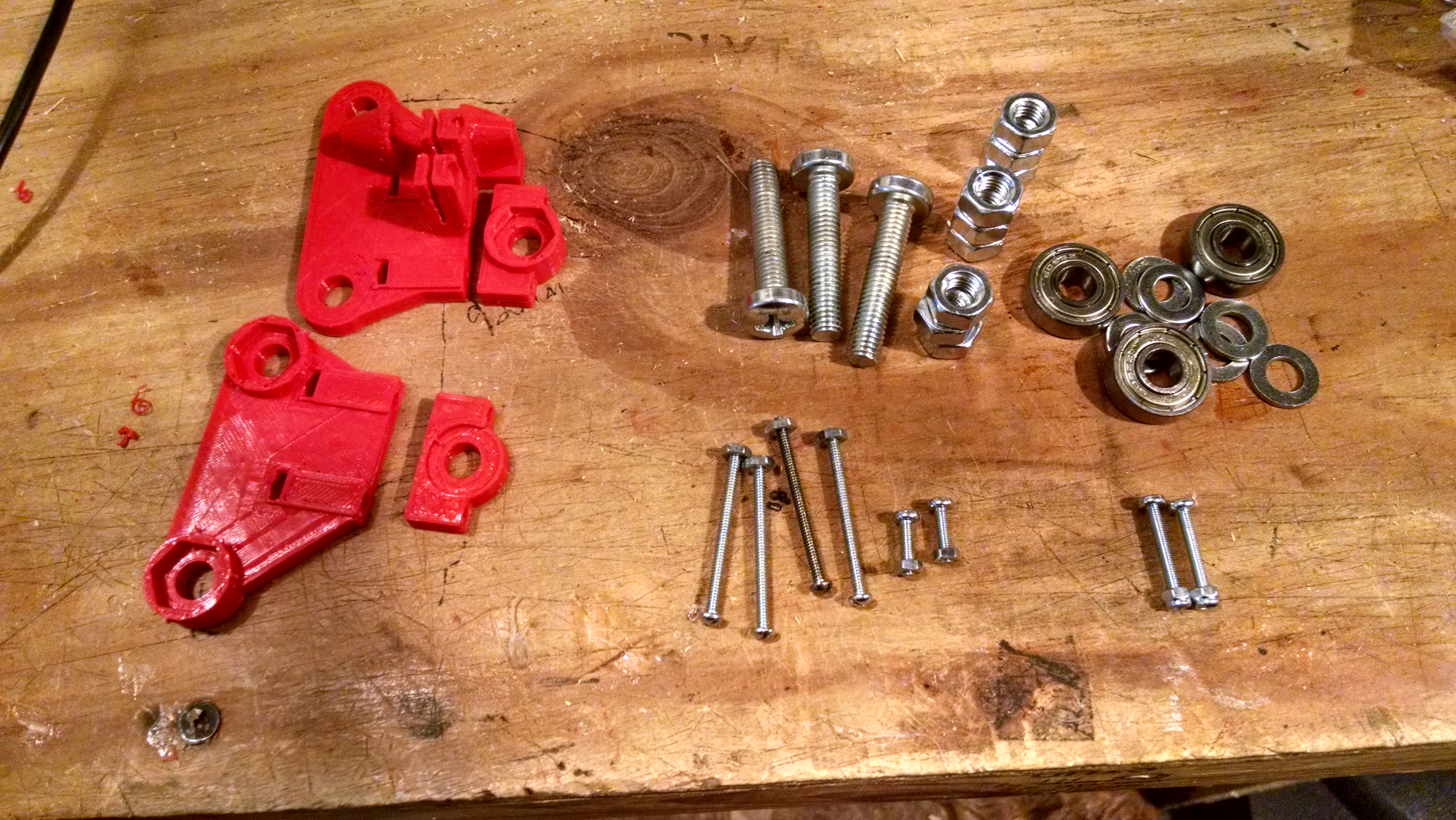
I did a thorough unpack and tried to sort everything into
per-component piles. The instructions don't really say which screw goes
where, so I figured I'd try to get that all sorted out before I used up
all of the rare screws on the wrong components. Here are my piles:
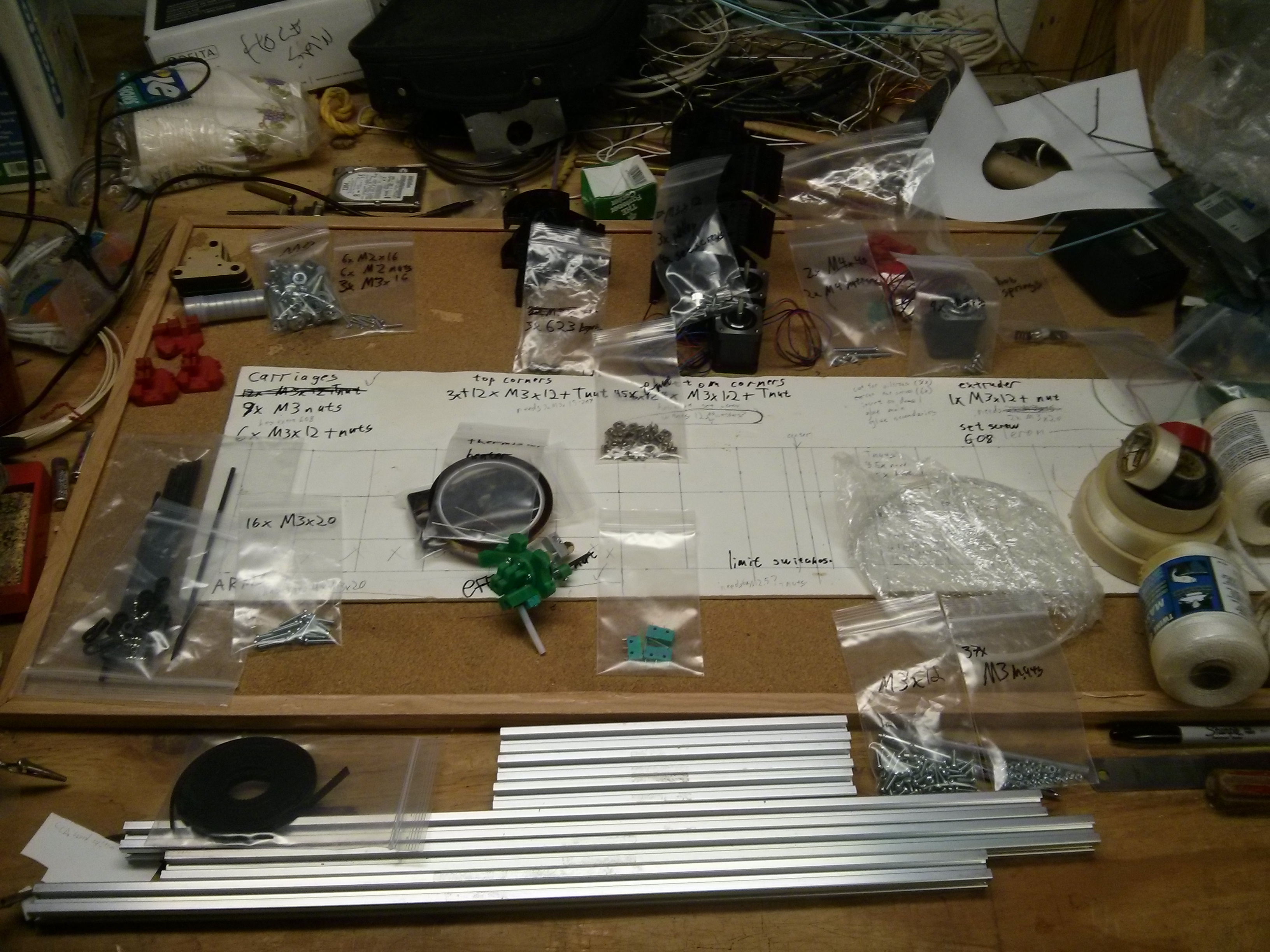
I came up with a short list of additional screws I thought I might need, and the hardware store blessed me with a good drawer of M3 parts! I'll detail these parts as I put the components together, but I bought: 3x M2.5x12 with nuts (for limit switches), 3x M3x16 (for idler pulleys), 12x M3 nyloc nuts (for Traxxas ball joints), and 12x M3x25 (for Traxxas ball joints). Altogether under $15.
I think there's a way to get by without most of those purchases -- the kit isn't necessarily wrong -- but for various reasons I prefer to have them on hand.
It is super reassuring to have sorted out the components. I really am not missing anything essential except the 6x 240mm beams, and I can envision how this will all go together!
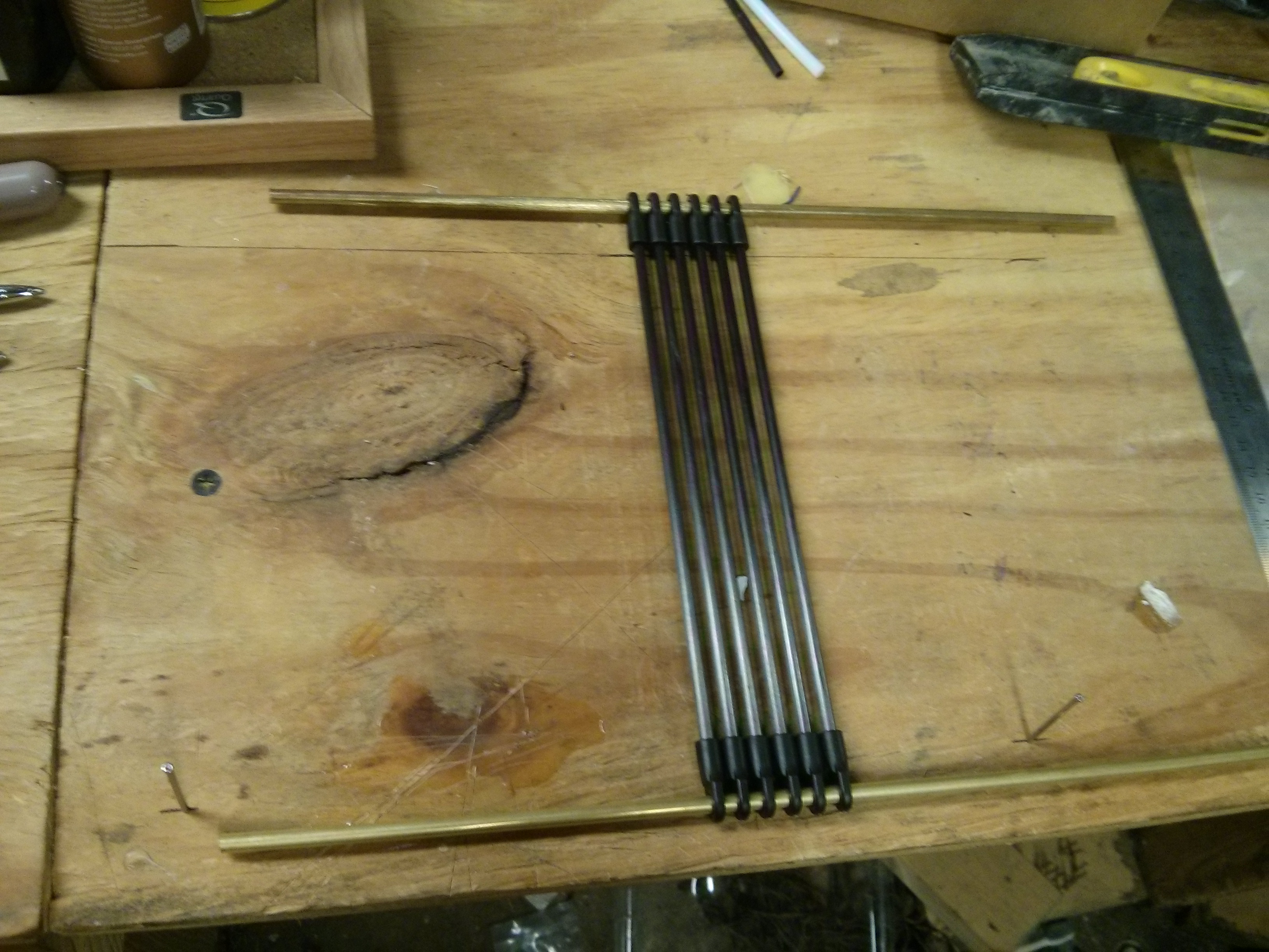
I decided to start with gluing the carbon fiber rods to the Traxxas joints. They gave me 8x 180mm carbon fiber tubes that fit inside of the Traxxases. They fit *very* snugly. In fact, it's kind of a pain to adjust them once you've inserted them, which is probably why Mixshop gave me 8 rods instead of the 6 that are needed -- I managed to break one while twisting the Traxxas into alignment.
It is important that they are all the same length (or the end effector
will be tilted), and they also should be all oriented the same direction.
To ensure this, I got brass tubes that barely fit within the Traxxas
ends. So I got them all in a straight line. But the ones on the left
were a little shorter than the ones on the right, so I re-ordered them
and made them a straight line again, and kept on repeating that process
until they really were all the same length. What a tedious pain in the
butt. Then I painstakingly straightened the ends so they were
aligned:
At that point, I put a couple small drops of epoxy where the rods and joints meet. I probably didn't really need to glue them, and that isn't the strong way to glue them, but I didn't want to be working with an epoxy-contaminated mess while I was straightening them all out!
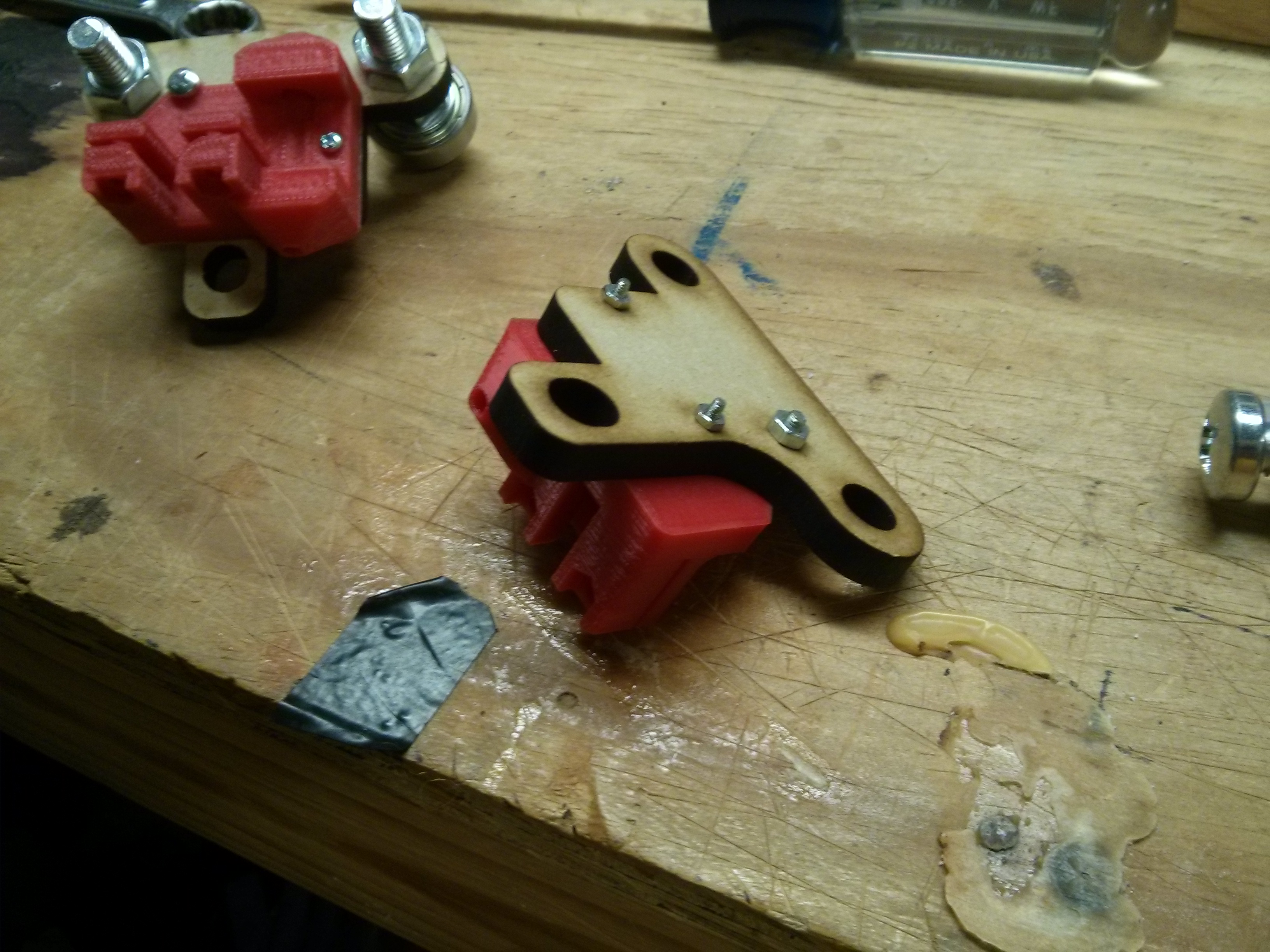
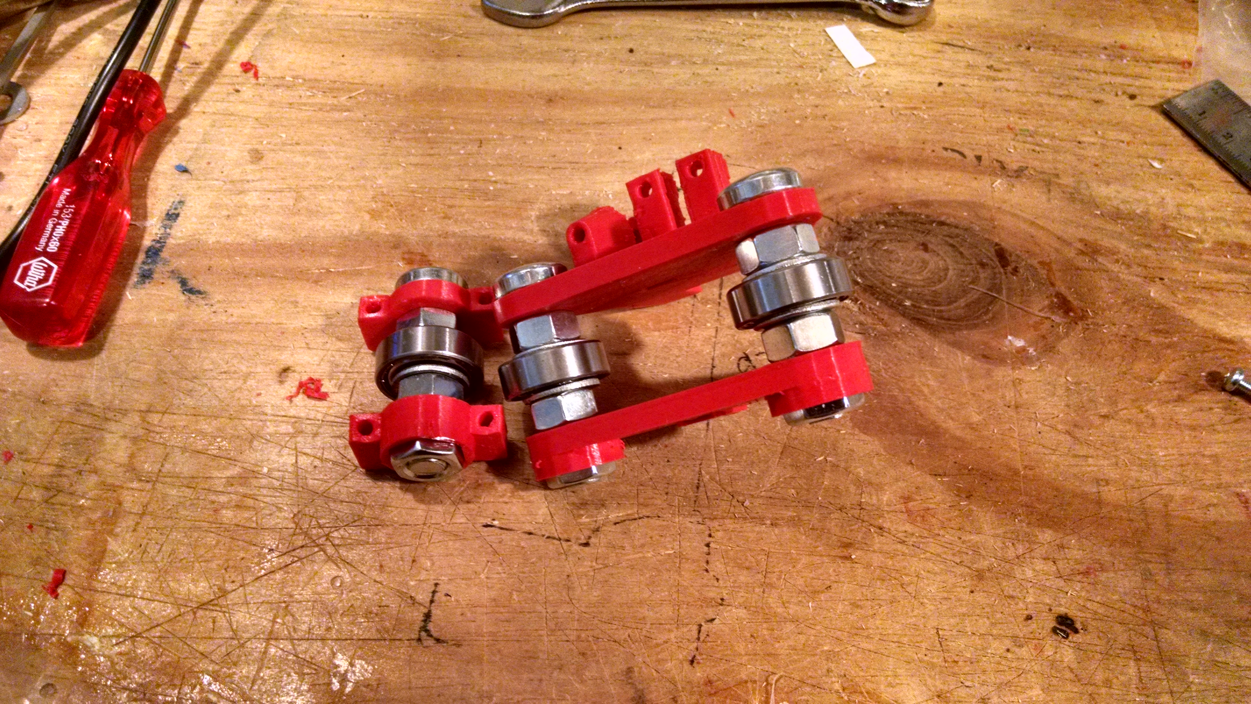
First I connected the plastic and wood parts. Each carriage uses 2x
M2x16 and 1x M3x16, and associated nuts.
Each carriage needs 3 rollers. On the M8 screws, I put one washer,
one bearing, one washer, then a nut:
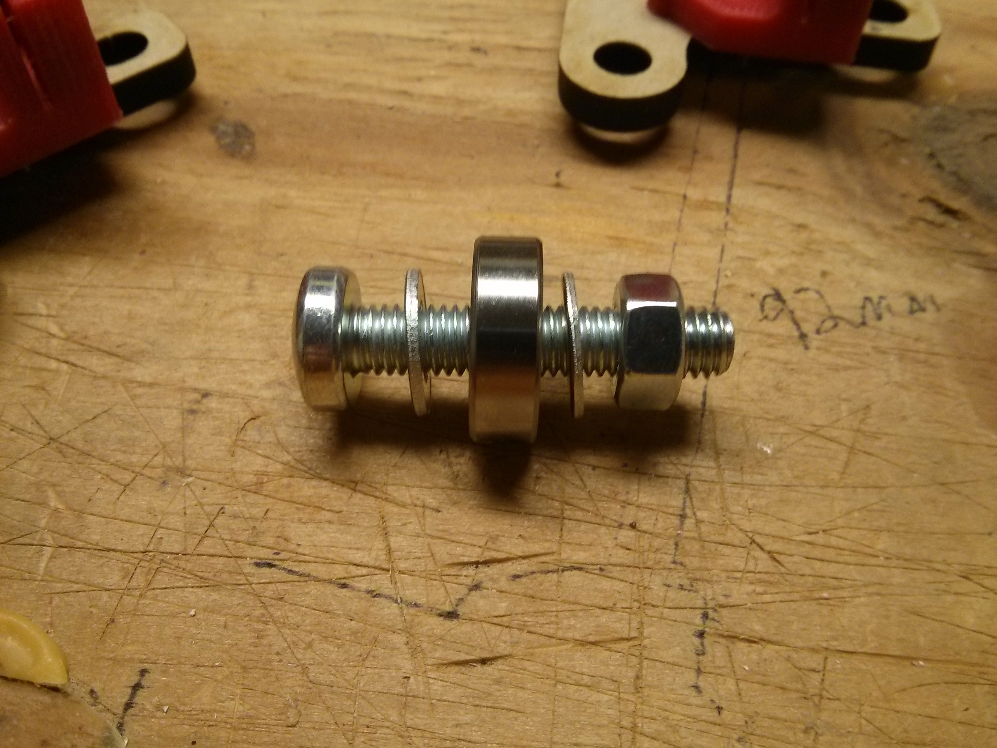
I snugged up the washers around the bearing, and then put it through a
hole in the wooden carriage (make sure the rollers are opposite from the
plastic), and added another nut. I tightened the nuts
just by using a screwdriver and a 13mm wrench on the exposed nut. The
bearing prevented the inner nut from rotating relative to the screw. One
of the nuts potentially conflicts with the plastic component, so I would
at least test-fit the plastic component first.
They gave me 9 extra M8 nuts, and the bolts are long enough you could put an extra one on the end and use it as a lock nut if you wanted.
They also gave me 3 extra laser-cut wood pieces. I didn't break any of the pieces they gave me, but I did tighten the screws down hard and I was afraid of breaking them. The laser-cut wood sure does have a nice fireplace aroma!
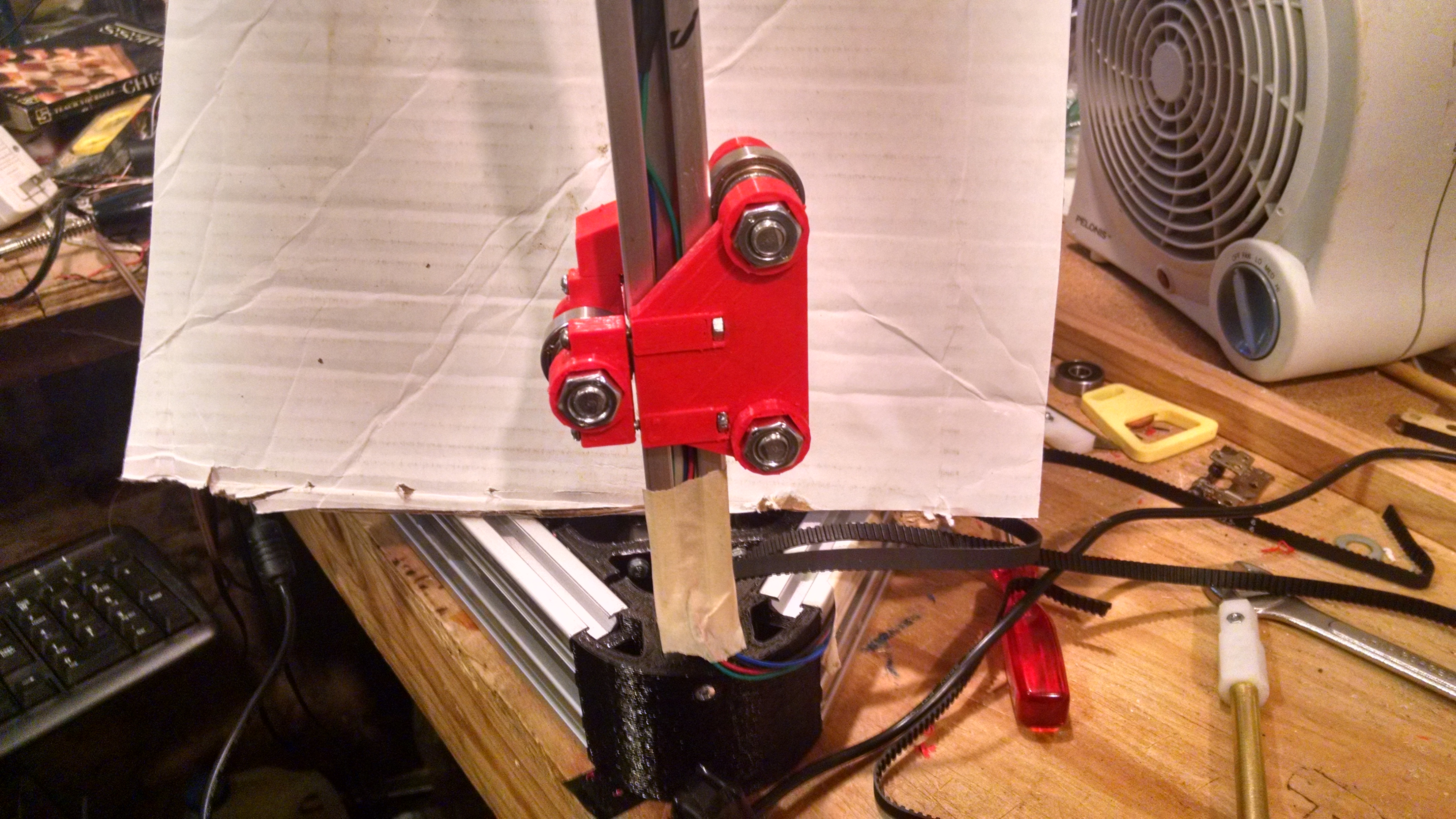
I didn't give any attention to the alignment, I just put it together the way it wanted to go, and it very nicely grips the rail with a nice degree of tension -- I am very impressed! It looks as if the beam was designed to accept these bearings.
While I was assembling the carriages, the mail man dropped off the remaining 6 pieces of 240mm beam!!! So I can keep going!
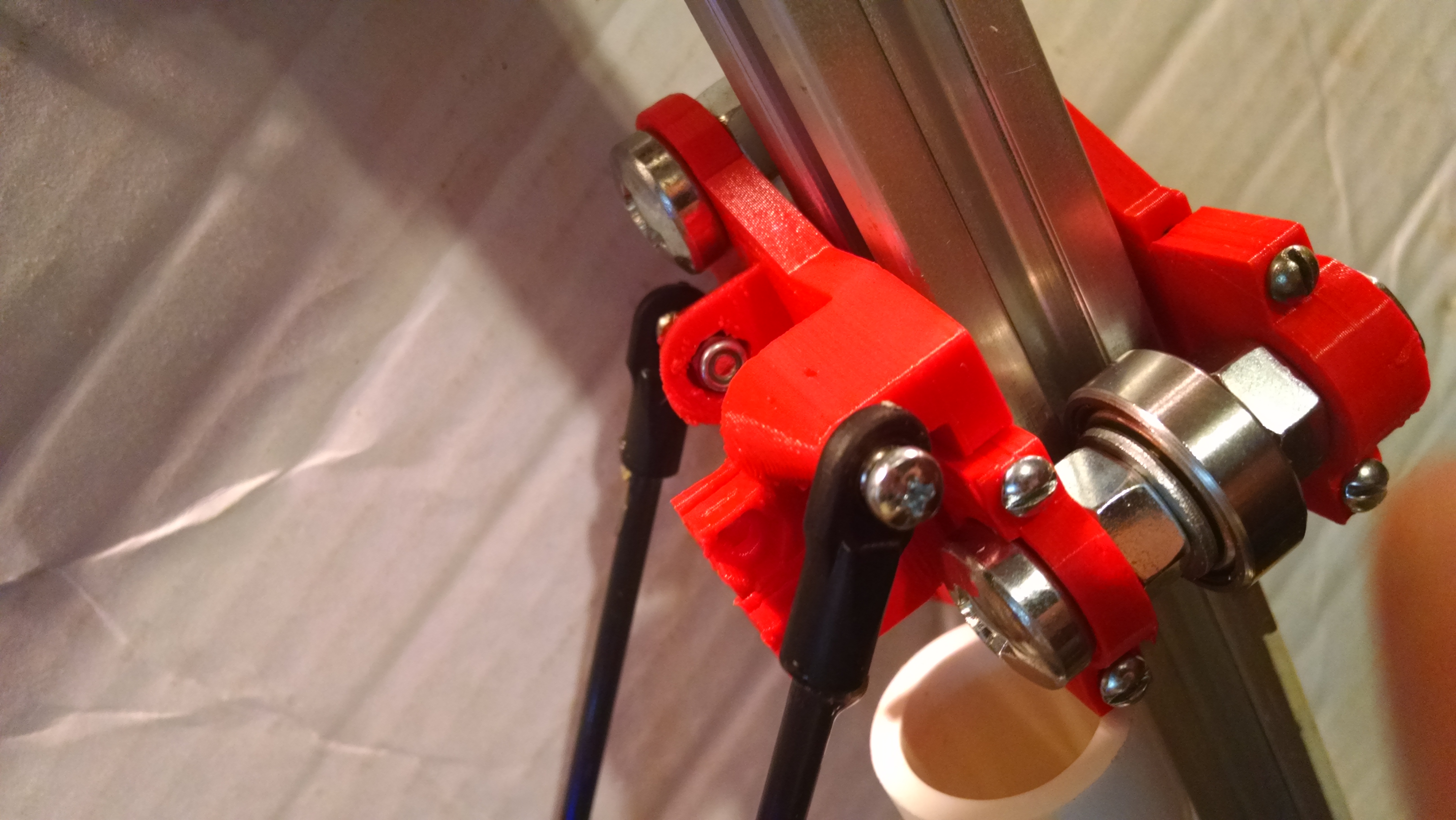
They only gave me 3x M3x16, and I didn't see any choice but to use
them on the carriages. So these are ones I bought separately. You *can*
use M3x12
for this, but it doesn't have much overhang. Put the bearing on the
M3x16 and insert it into the gap in the top of the bracket.
I had to clean up the plastic a little bit. Be careful not to shave
off the nubs that keep the bearing centered in the gap. I used a heat
gun for 5 seconds directly on the gap, and that made it very easy
to shove the screw into position with a thin-blade screwdriver. Smells
kind of sweet when hot, I guess they used PLA.
Then assemble the triangle using the M3x12s and T-nuts. Because they used a beam that takes these T-nuts, you don't need to slide the nuts inside the beam, you can just insert them directly where they go in the slot. That makes inserting the last beam into the triangle much less delicate.
It's kind of a pain getting the screwdriver into the inside of the plastic bracket, but if you have the correct sized philips driver it's not too bad. And it doesn't particularly need to be perfectly precise.
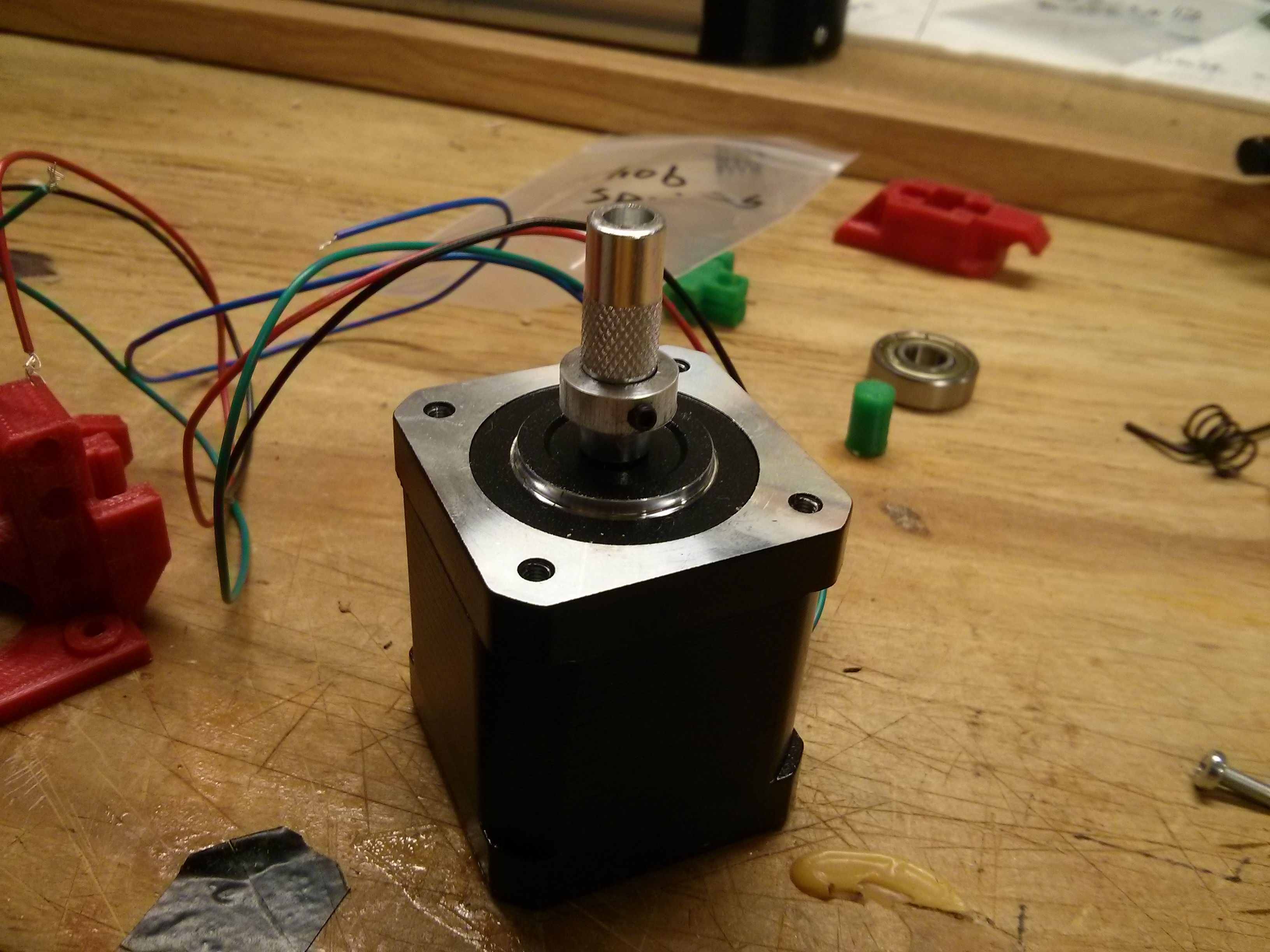
I put the set screws in the pulleys and put the pulleys on the motors.
The set screws use a 1.5mm allen wrench, but you probably don't want to
tighten them down just yet.
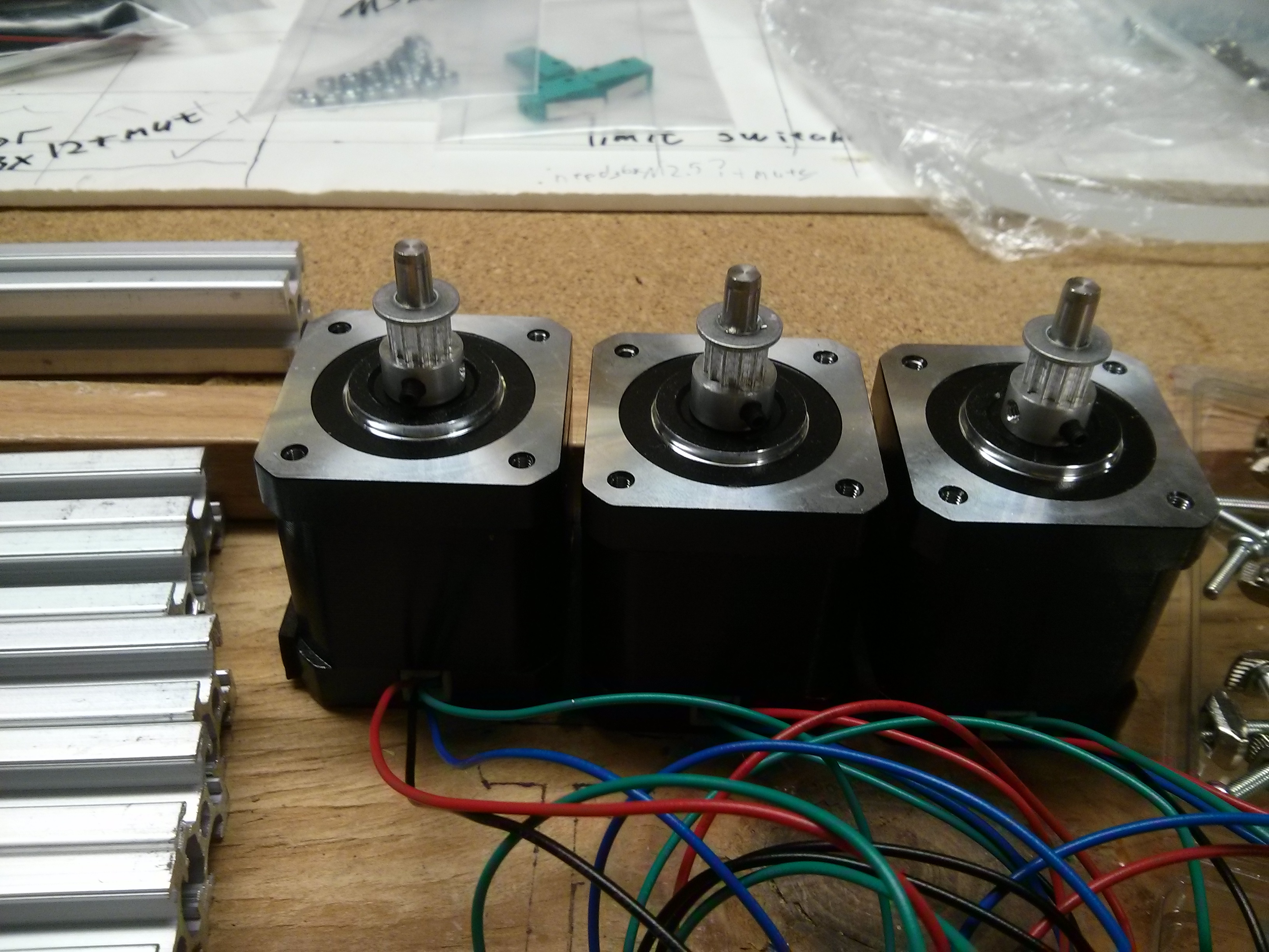
Then I attached the stepper motors to the plastic brackets. I lightly shaved the edges of some of the screw holes with an x-acto knife to get the screws to align.
The kit comes with 12x M3x12 hex head screws, which are clearly for the stepper motors because the hex heads can be tightened even in this tight space. However, they were *just* too long -- they bottomed out in the stepper motors before they were quite snug against the plastic. So I bought 12x M3 washers from the hardware store, and they took up the tiny extra space.
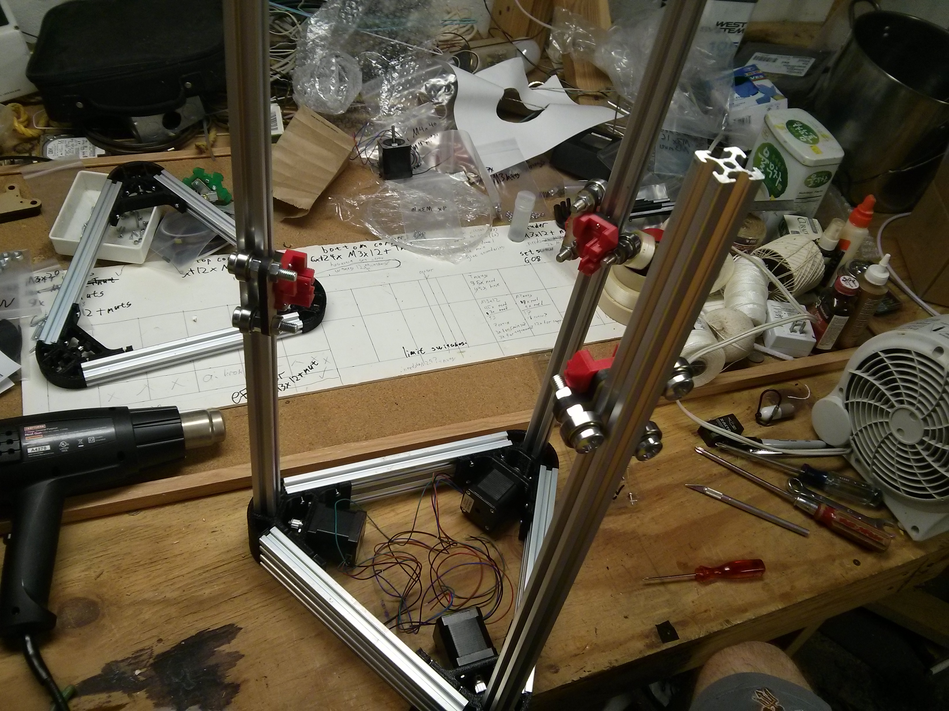
At this point, I laid a top corner piece over the bottom corner piece, to see where the pulley should be to match the bearing on the top. Then I tightened the set screw to hold the pulley in this alignment.
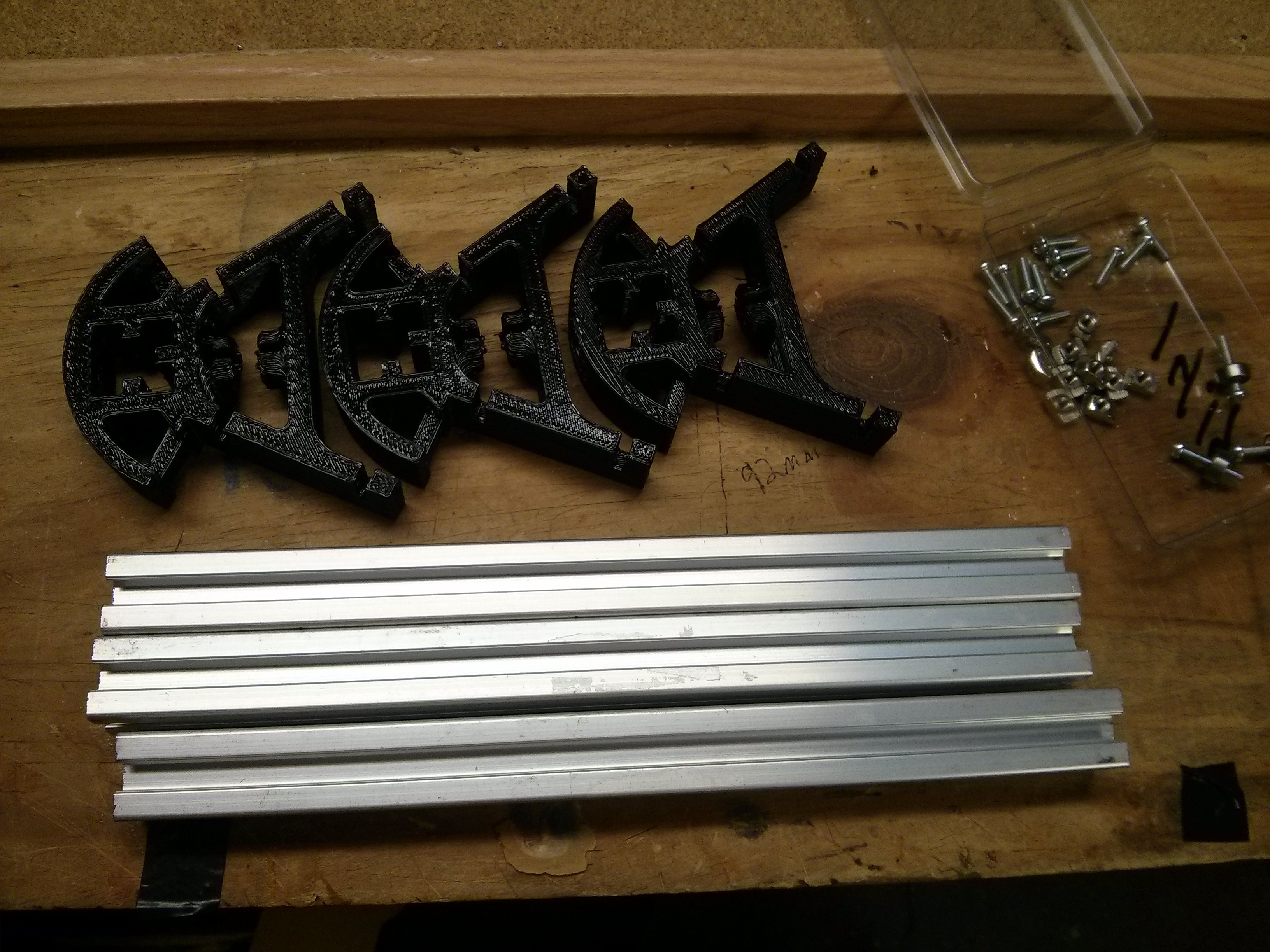
Then it's just a matter of assembling the triangle -- two of them this time.
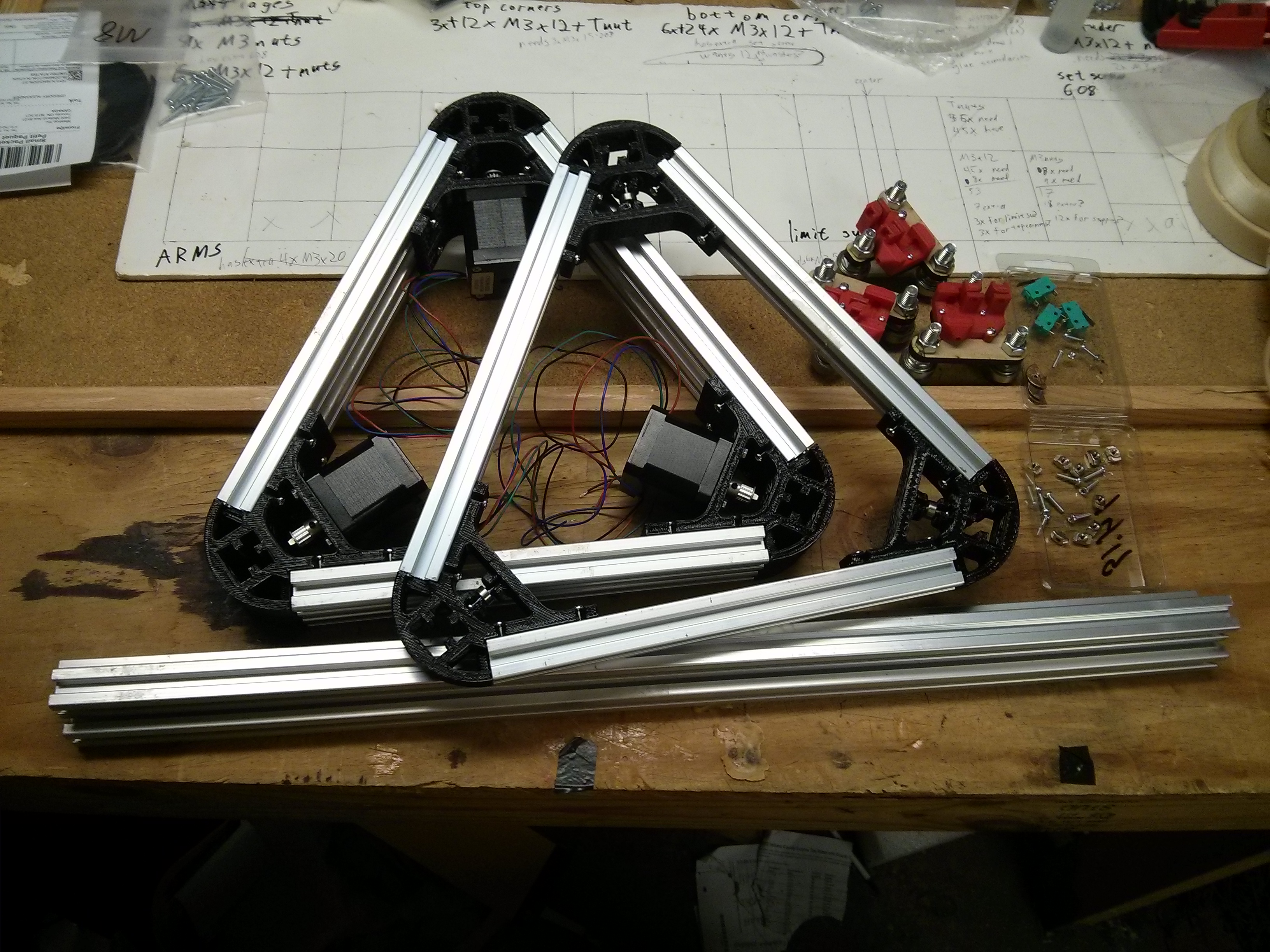
First, I inserted the M3x12 screws into the holes in the outside of
the triangles, with a T-nut on the end of each one:
Then I inserted the 3 beams into the bottom frame and tightened them down. Note that bottom frame is not quite symmetric, and I think you want the stepper motors to be closer to the top than the bottom. They didn't want to go, so I used the heat gun for 10 seconds on the openings before jamming in the beams. You have to be careful that the T-nuts don't wedge it, because if they do, pushing harder won't solve that problem. I still had to use a decent amount of force. It did not break. Knock on wood.
Now is a convenient time to insert things into the inside beam slots.
I started by threading the 3 carriages onto the beams.
Then I needed to add the limit switches. The holes in the limit switches are big enough for M2.5 screws, but not big enough for M3 screws. I think Mixshop intended for me to drill out one of the holes in the limit switch and use an M3x12, but that would only solve half the problem. I've now used up all of the T-nuts, so I would have to use a regular nut on the back of the M3x12, which I'm not sure if that is really kosher with these beams. But mostly, I didn't feel like drilling out the switches.
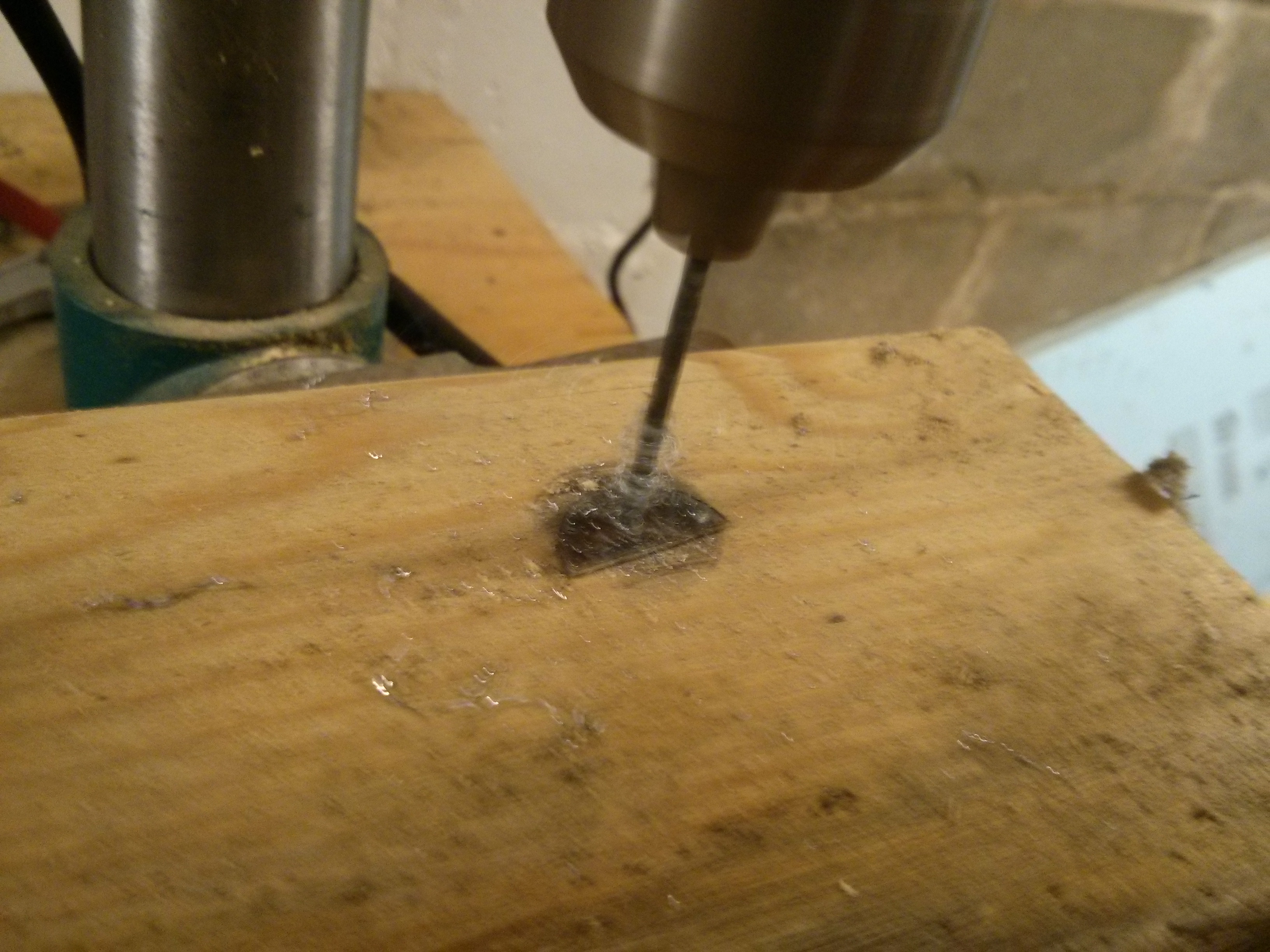
So I bought M2.5x12 screws and M2.5 nuts at the hardware store. But
the M2.5 nut doesn't even begin to engage the beams. So I needed a big
M2.5 washer. The only suitable blanks I found on my workbench were US
pennies. So I cut them in half (score with electrician dykes, then snap
in a vice), and then drill pressed a hole through them:
So on the M2.5x12 screws, I assembled one limit switch, one copper
washer, and one nut:
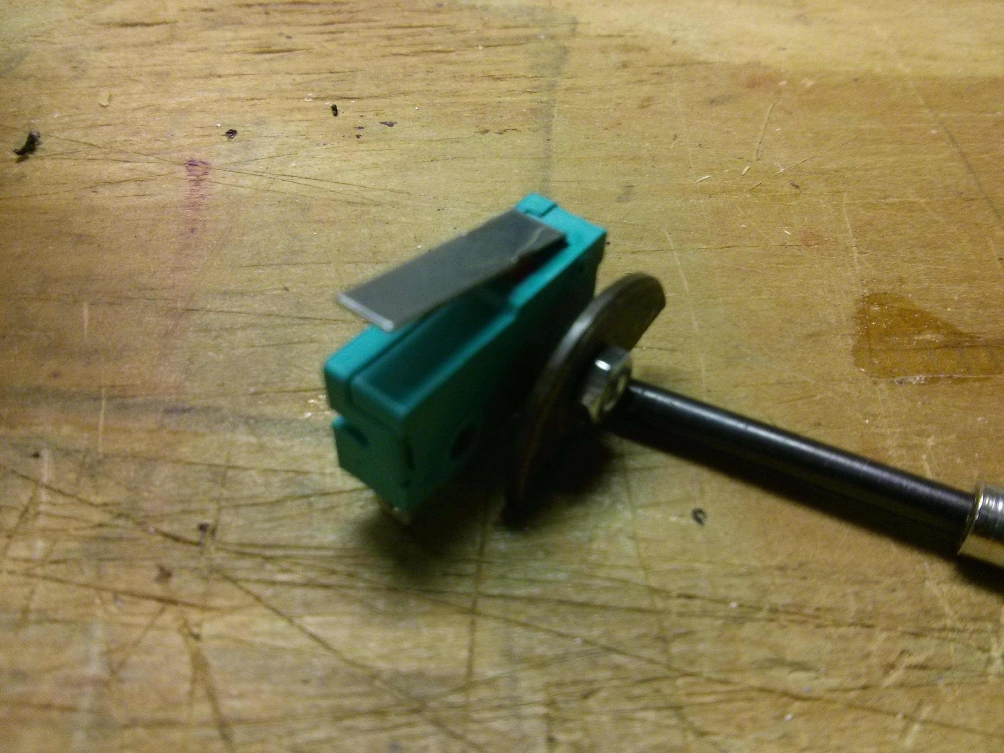
Then I threaded them into the slots:
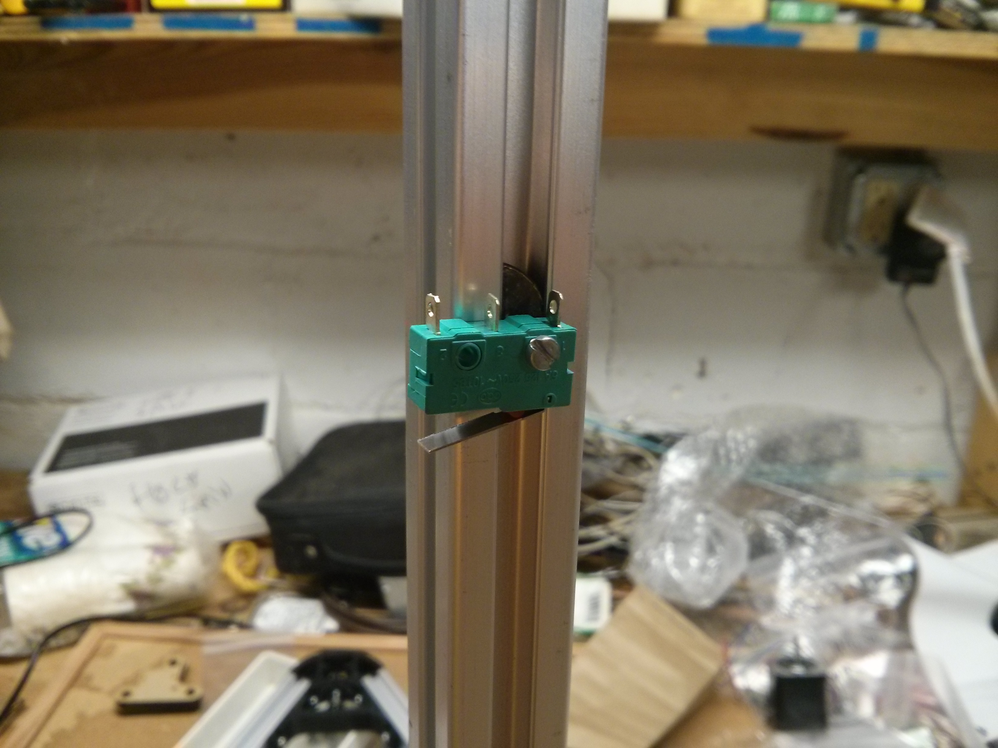
I'll align them later, I'm just sliding them on for now.
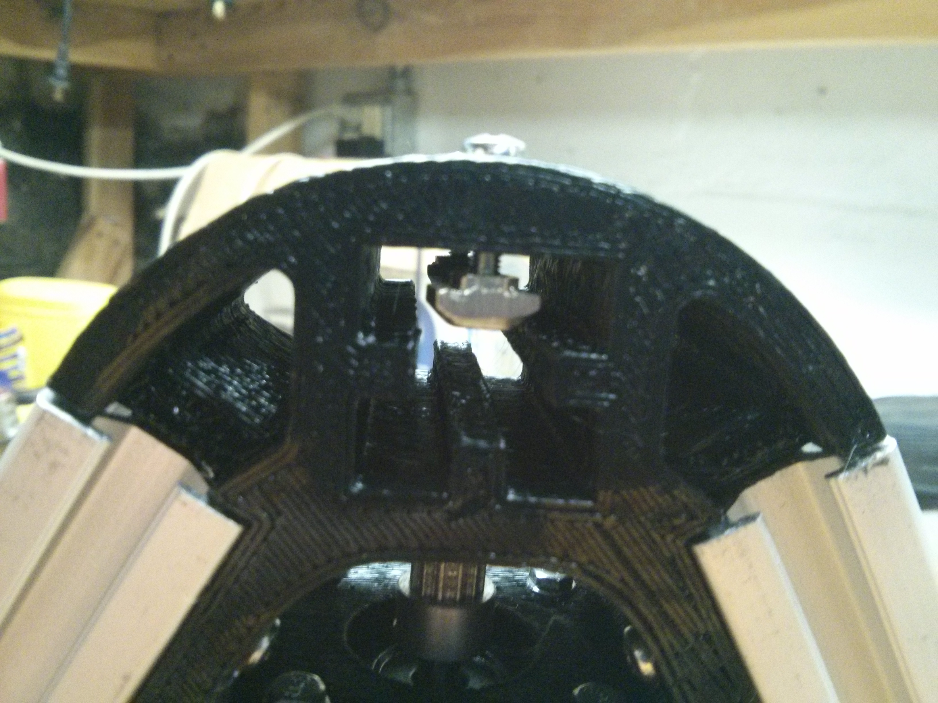
Then I put the top triangle on. Make sure it is right side up -- the bearings should be supported so that they will not fall out when the belt is tensioned. I had to heat gun all three corners at once, and then I kind of brutally wham-wham-whammed it on with the palm of my hand. Tighten that down and you're done with the main frame.
First I put the hob on the stepper motor. This time I did tighten
down the set screw.
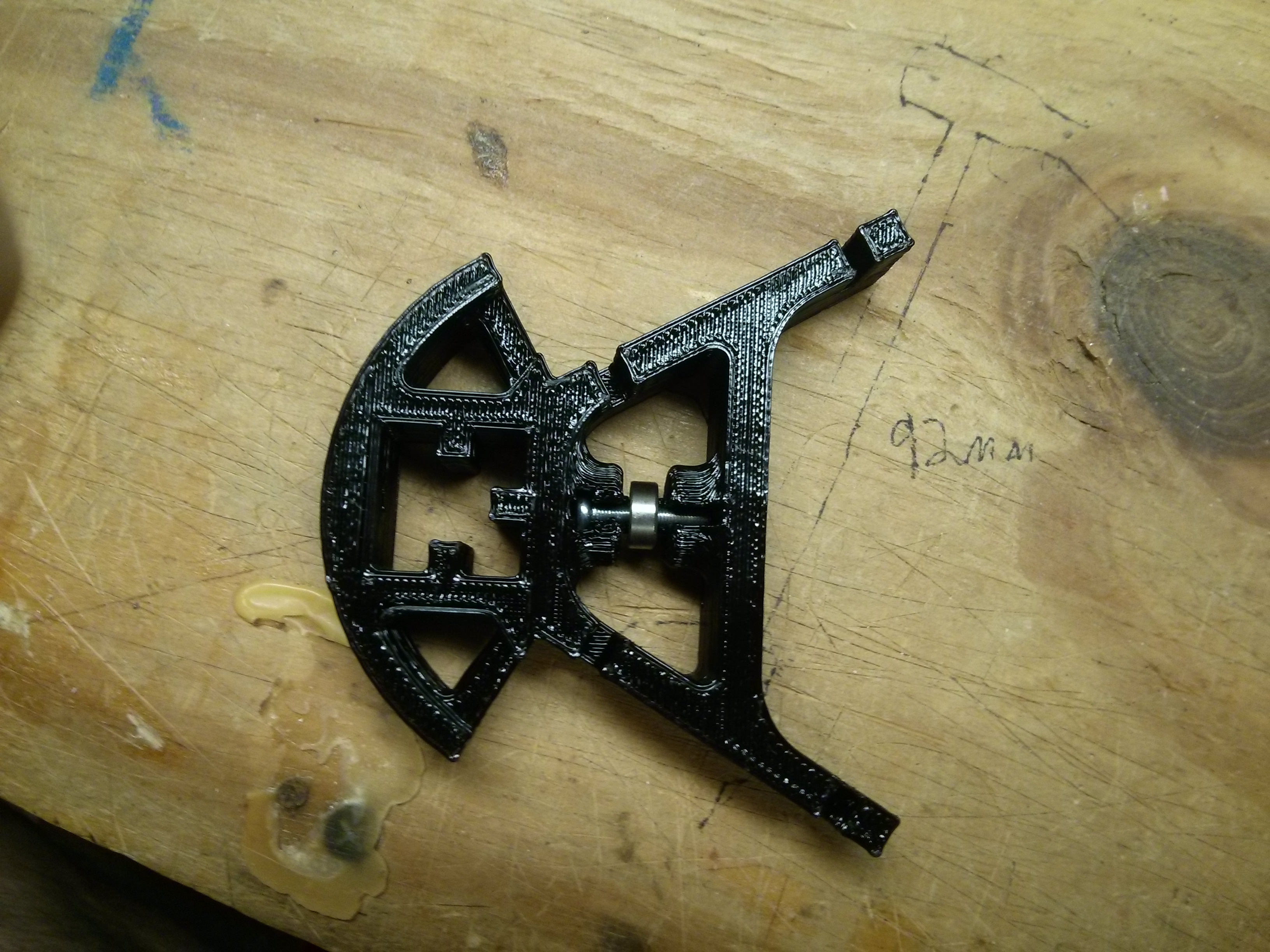
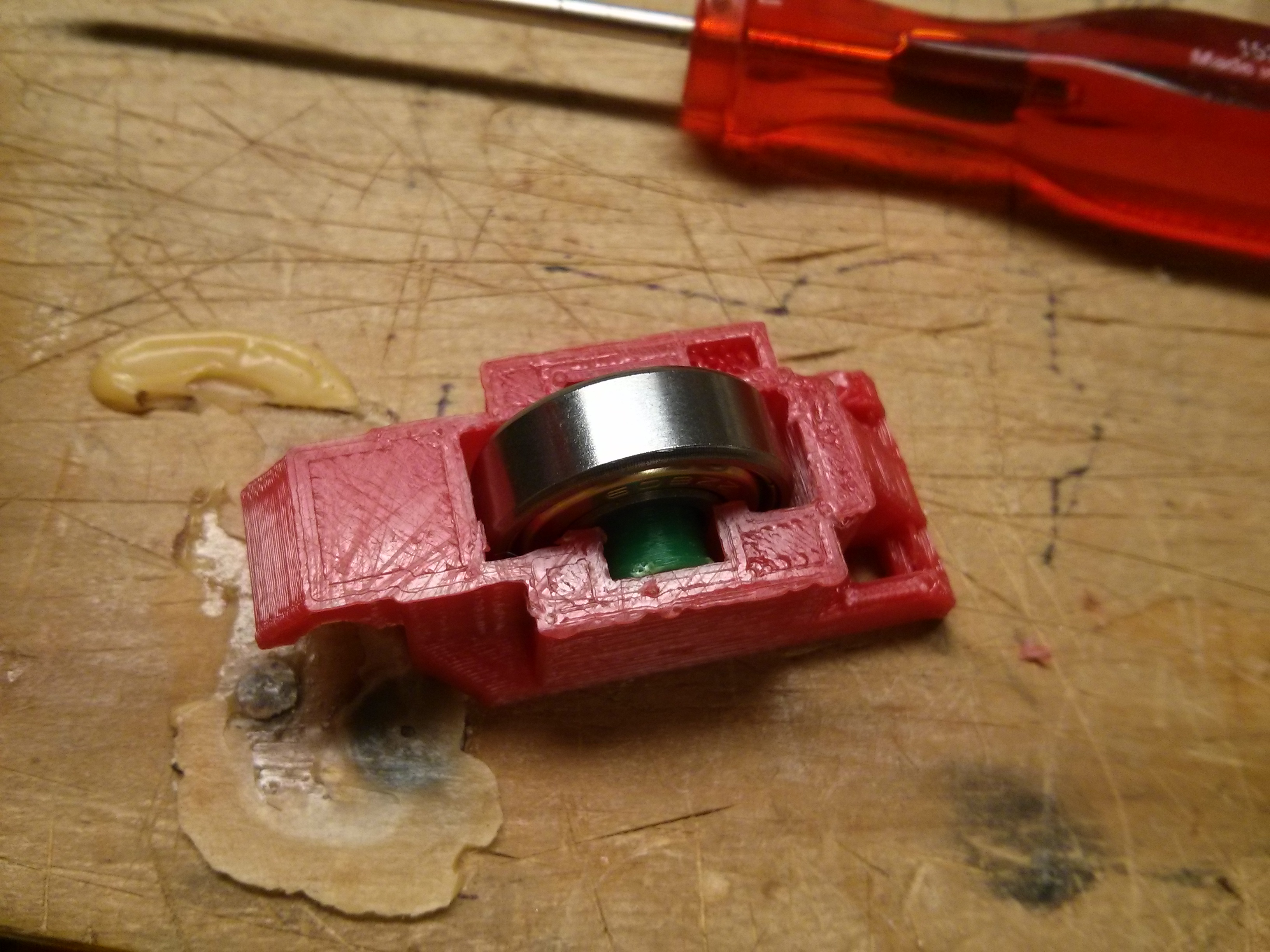
Then I put the bearing and its axle in its holder. I had to shave the
slot to fit the bearing into it, because it was the bottom layer of the
print and it had spread out a little bit.
I attached the stepper motor using the M3x10 and M3x20. They are *precisely* the right length (they bottom out in the stepper motor's holes), so you might want washers so you can actually tension them.
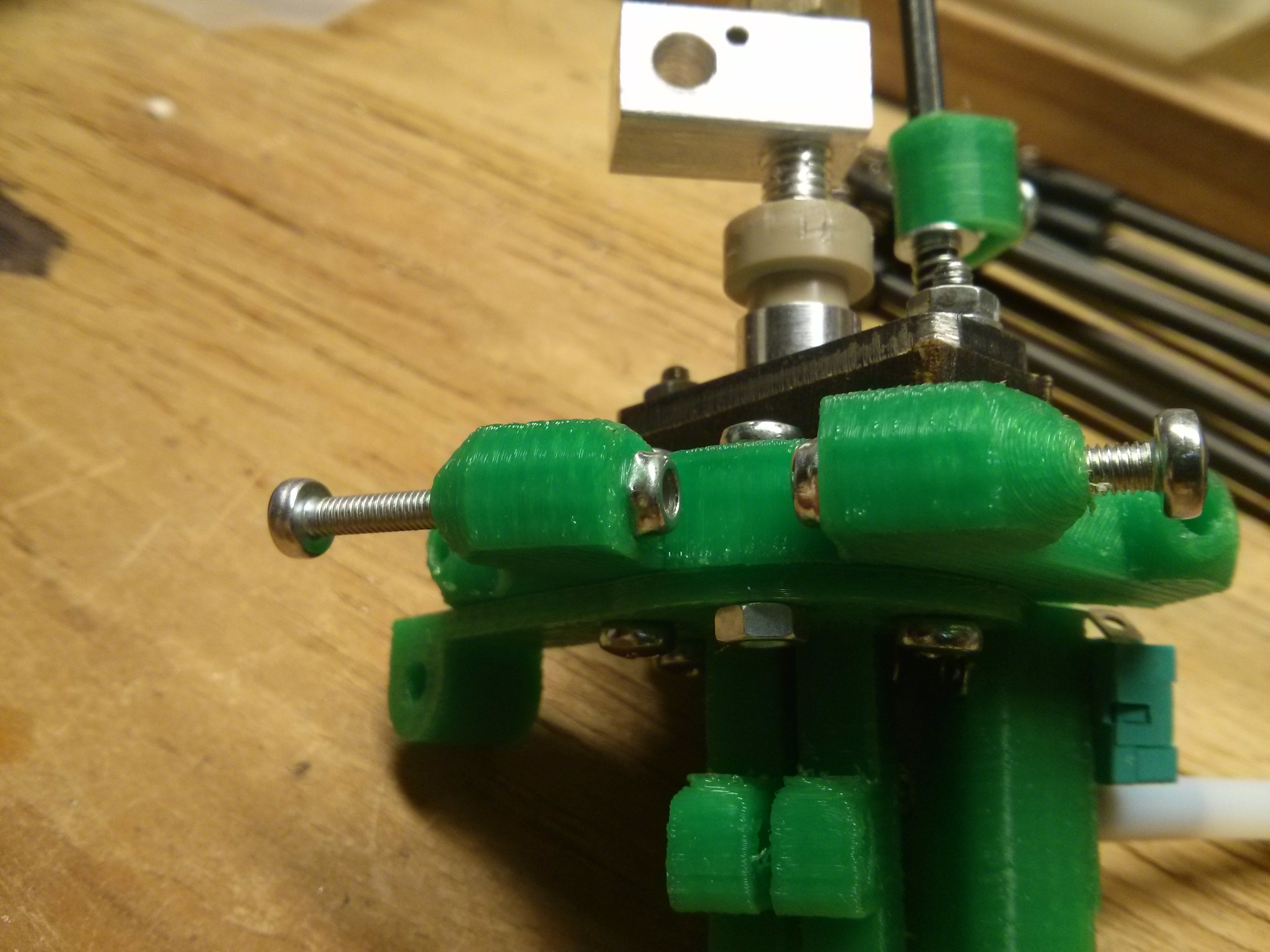
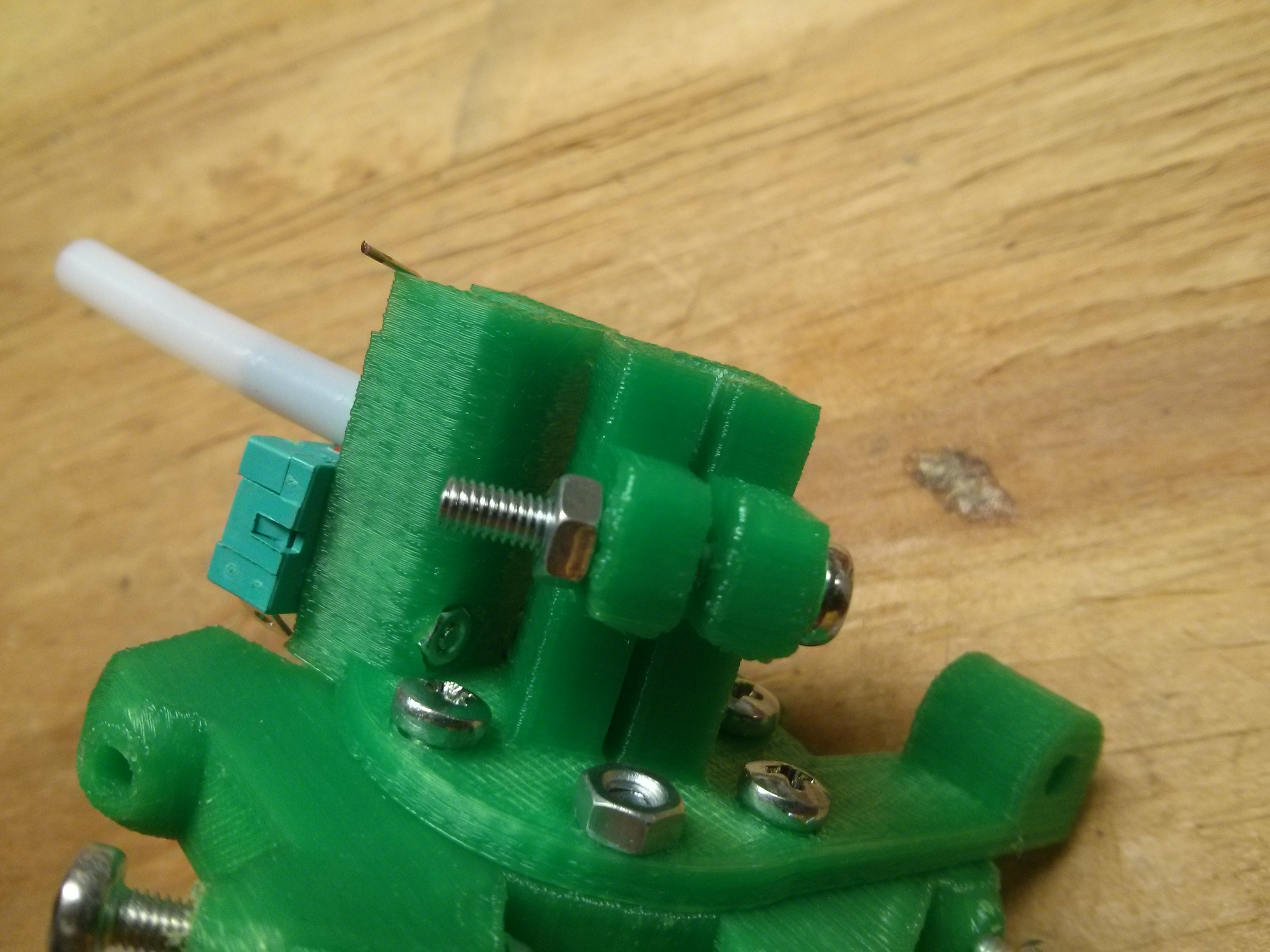
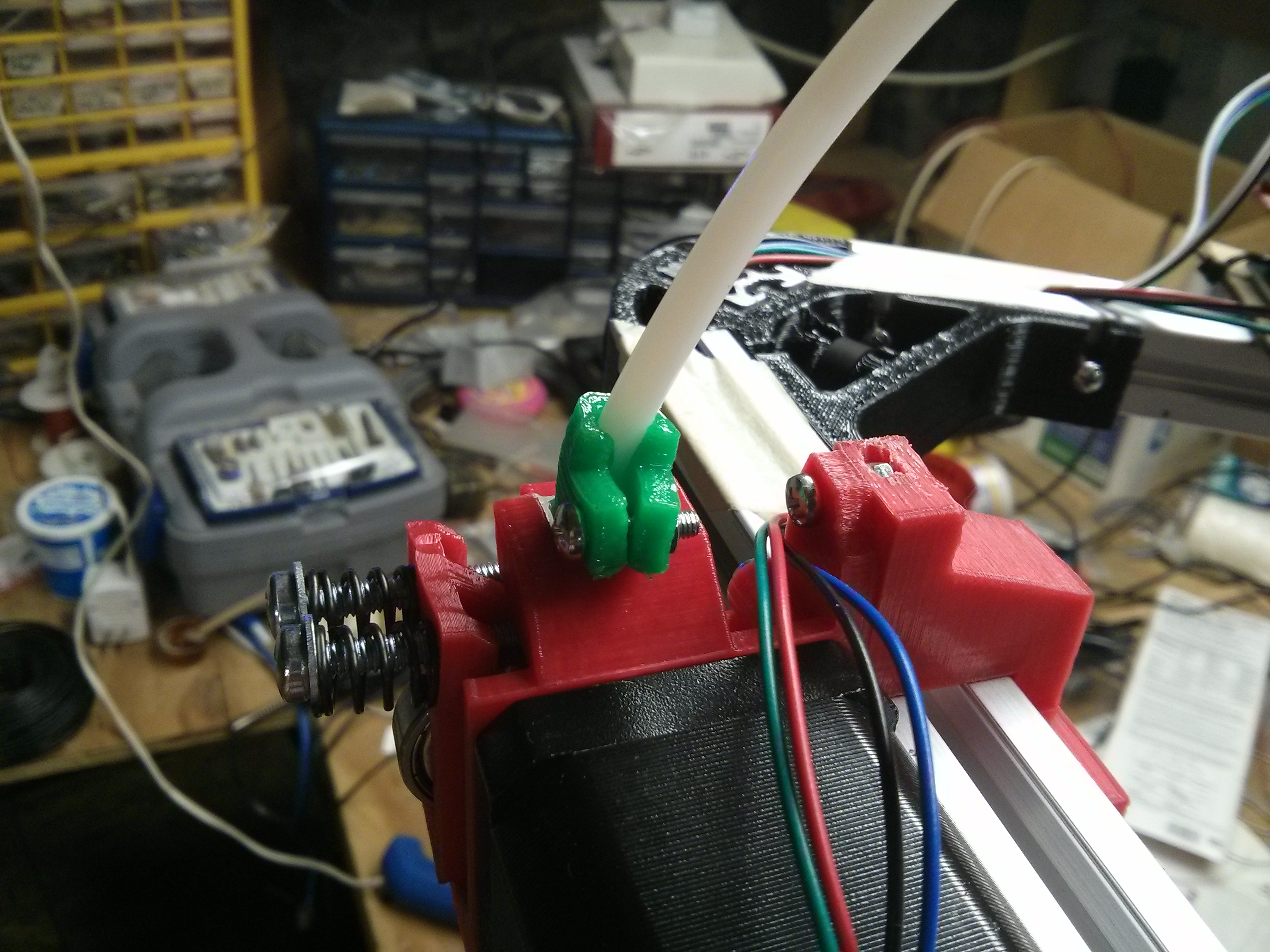
I put a washer and a spring on each of the M4x40 screws, and used those to attach the bearing holder to the extruder (you have to put the M4 nuts in the traps on the extruder first). You don't want to tighten these at all yet, so you can easily feed the filament through to get it started.
I put the M3x12+nut in the PTFE connector. Had to heat the plastic to fit the nut in. It's important not to tighten this screw while the plastic is warm, or you will bend it instead of tensioning it. The PTFE connector slots onto the top of the extruder. It is a little sloppy, which would potentially introduce hysteresis in the filament feed, so I packed it with hot melt glue just so it wouldn't move.
Next, I attached it to the top triangle of the frame. Instead of using
regular surface nut traps, the clamp has enclosed nut traps. I couldn't clear
out enough of a gap to feed the nuts in with my x-acto, and the heat gun
softened the wrong parts. So I used the Dremel and it was kind of a
pain. I'm not sure why Mixshop chose to do
it this way, instead of just using M3x16 or whatever screws that go
entirely through the clamp. I did
eventually get the M3 nuts in:
Then it was just a matter of using the M3x10 screws to clamp it onto
the frame:
That's enough for today. I still need to assemble and mount the hot end, wire it up, and then test/calibrate. Exciting!
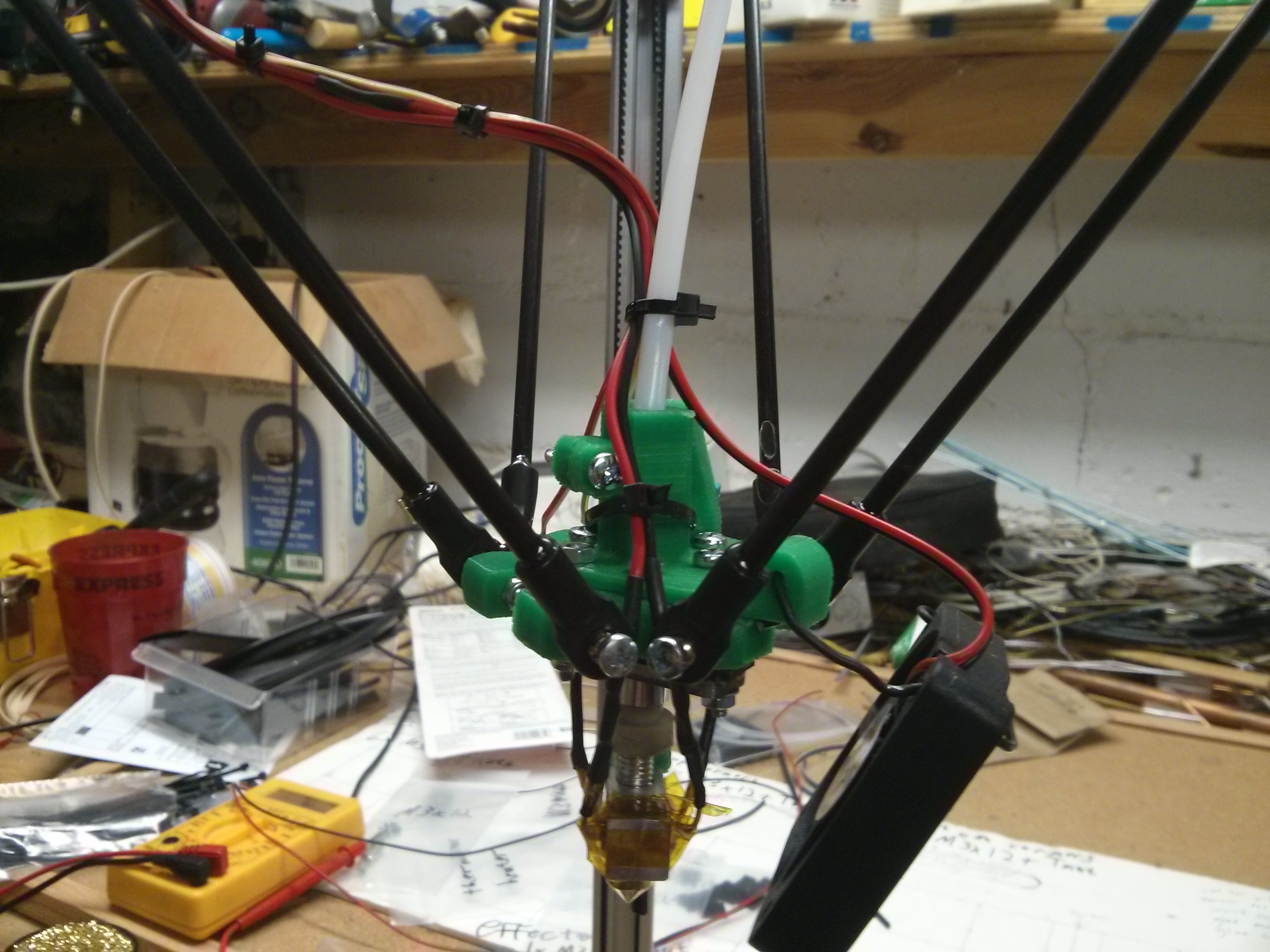
I put the balls in the Traxxas joints, which was harder than I
expected. I couldn't do it at all with my fingers. I first had
success using the needle-nose pliers like this:
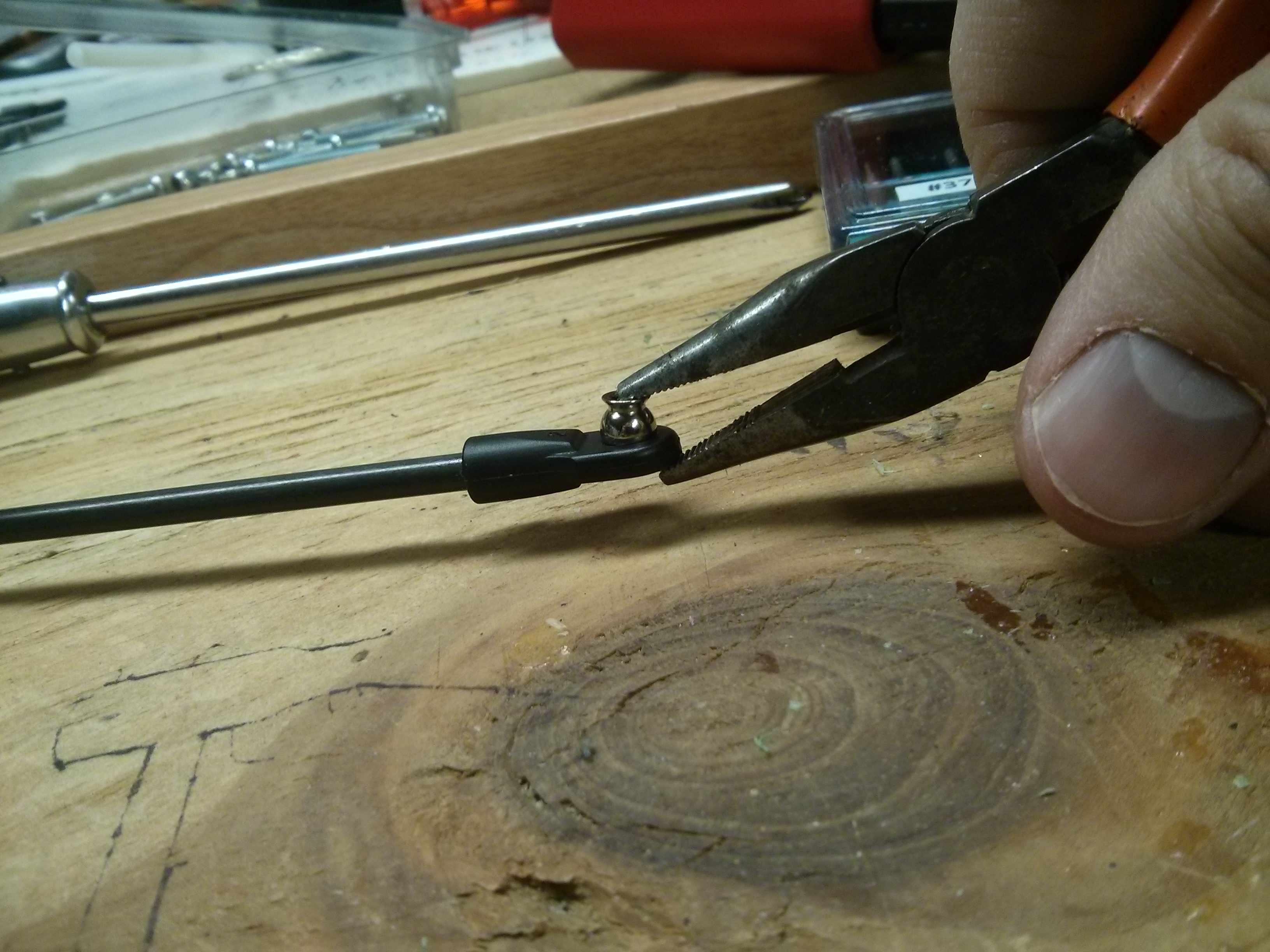
but that tended to push the balls so that they wouldn't go in straight,
and if they were at enough of an angle they actually gouged out a little
bit of the plastic part, and added a slight amount of slop!
So I switched to holding the pliers like this:
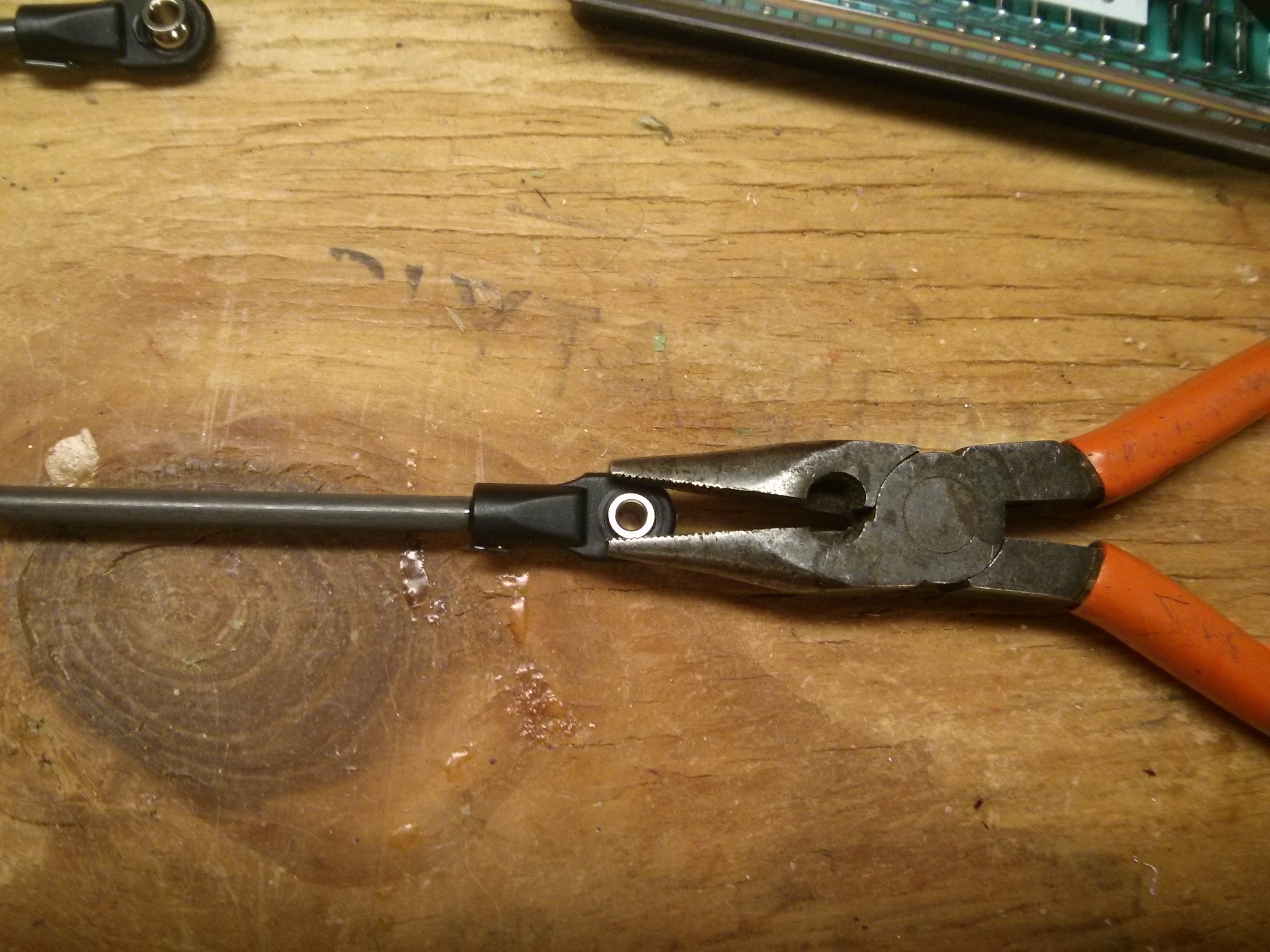
and just pushing down. That made it easy to visually verify that I
wasn't gouging the plastic. They should *snap* when they go into
position. If it is a steady resistance instead of a snap, that means you
are probably gouging plastic. Very nerve-wracking, you have to push very
hard without breaking anything, or flinging any tiny irreplacable parts
into the far corners of the basement.
I decided to use M3 nyloc nuts because that's what most of the other Kossels called for. So I had to buy those extra -- Mixshop only sent me regular M3 nuts. I'm sure it would have worked fine, it's just a question of how long it would take to loosen up. Note that you probably want to avoid putting heat directly on the nyloc nuts.
I put the M3 nyloc nuts into the nut traps on the end effector, so
they will be ready to hold the arms on. None of them just fit on the
first try, so I heat gunned the trap for 5 seconds. Then I inserted a
screw through the hole, and threaded a nut onto the tip of the screw.
Then I pulled on the screw, which was an effective way to pull the nut
perfectly into position. I left screws threaded through the nuts just as
a place-holder so the nuts would not wander off as I worked.
Even with a lot of heat, I couldn't get an M3 nut into the printed
PTFE connector's trap, which meant I could not use the M3x12 that I
think was intended for this purpose. No matter, I expect I will have
M3x20s left-over, so I used one of those:
I cleaned out the PTFE connectors with an x-acto knife. They hold the tube very snuggly without even using the tension screws, so I think it will work fine.
The depth probe was not very good at staying up when it was stowed. I just bent the safety pin slightly, and that fixed it up nicely.
My intent when starting this build diary is that I would document it more thoroughly than others have -- a lot of instructions seem to assume steps are obvious that I do not find obvious. However, looking back, I have left out as much as anyone else, just different things than others have chosen to leave out.
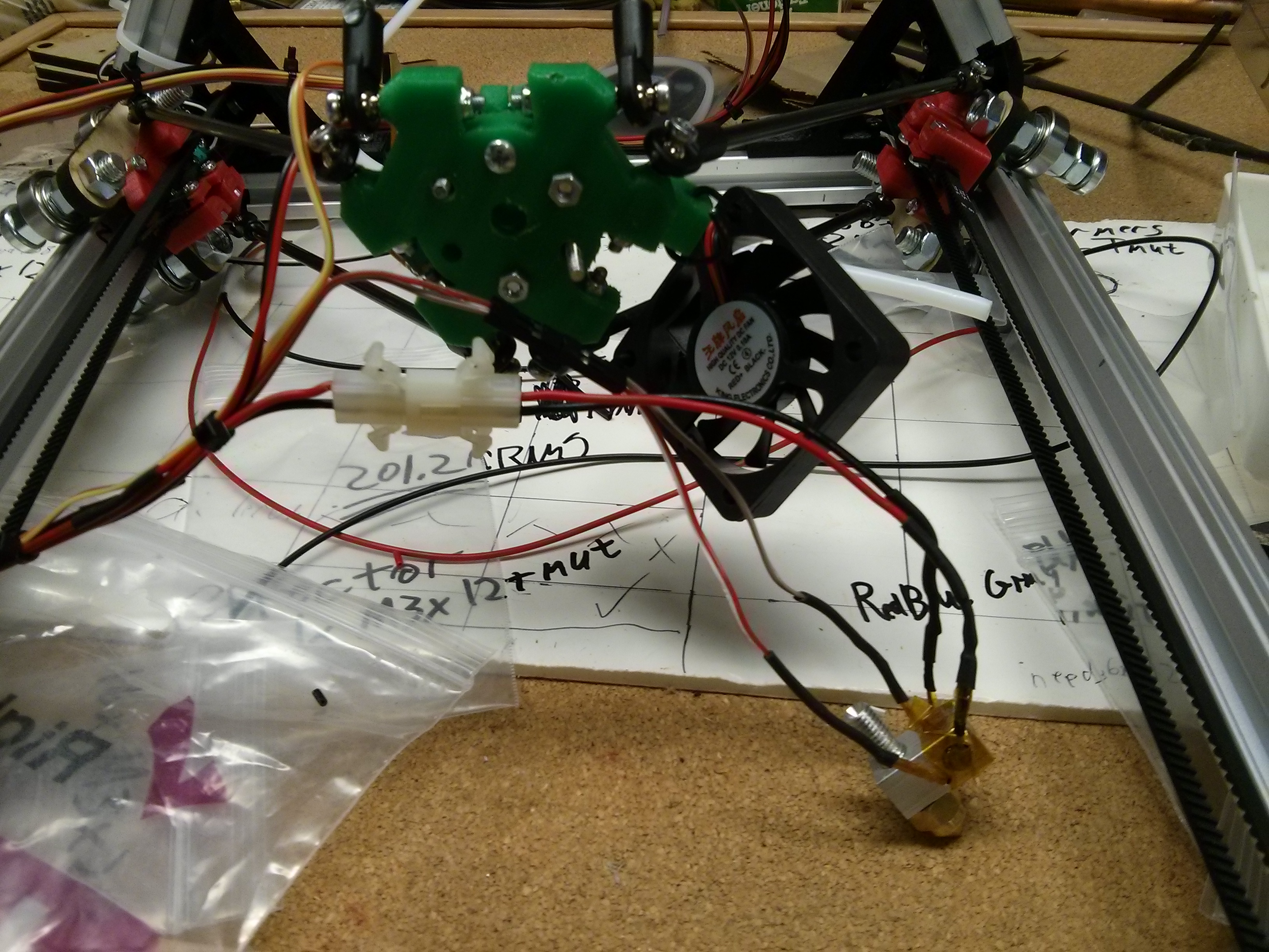
Which brings me to wiring. Mixshop doesn't give much more detail than
this diagram, which I have copied:
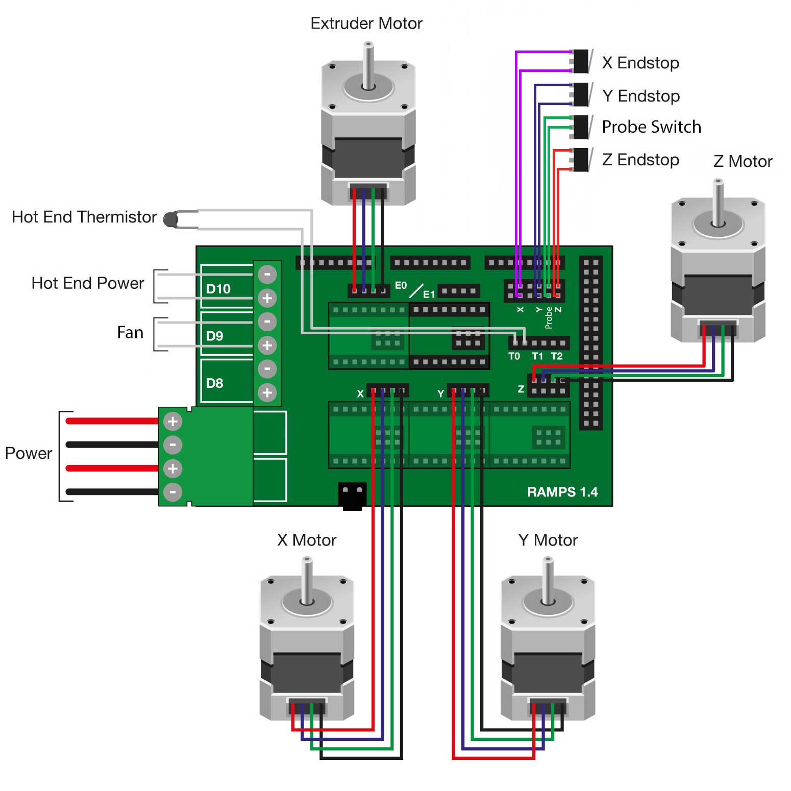
Which is really enough information, but here are some details. They just
provide a tiny thermistor, a large high-current resistor (heater), some
crimp female 0.1" SIP connectors, about 3 feet of 4 conductors of
red/black thick wire, about 6 feet of thin 10-conductor ribbon cable, two
little fans, and of course 4 switches and 4 stepper motors. You will
need at least solder, zip ties, and heat shrink tube.
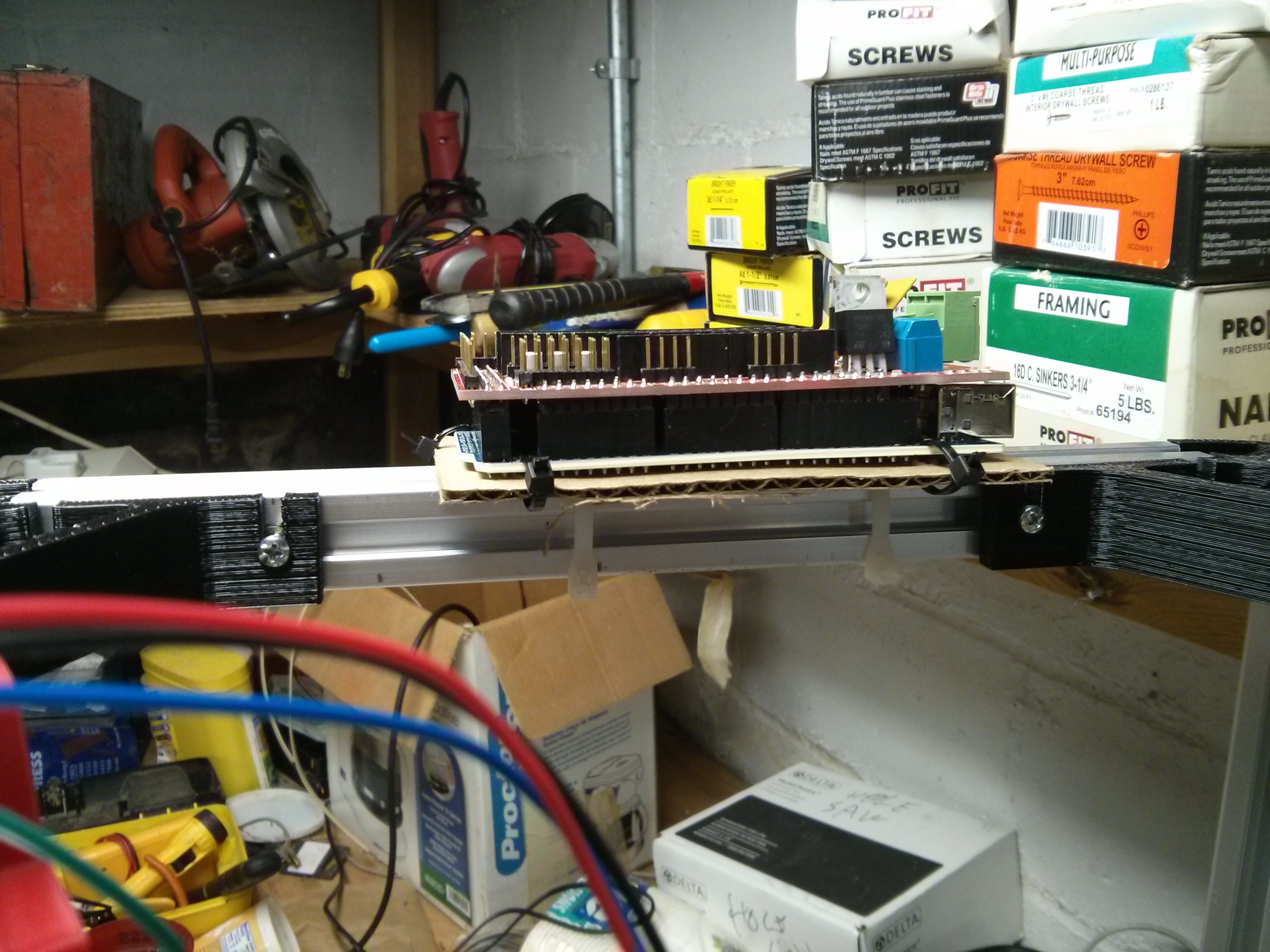
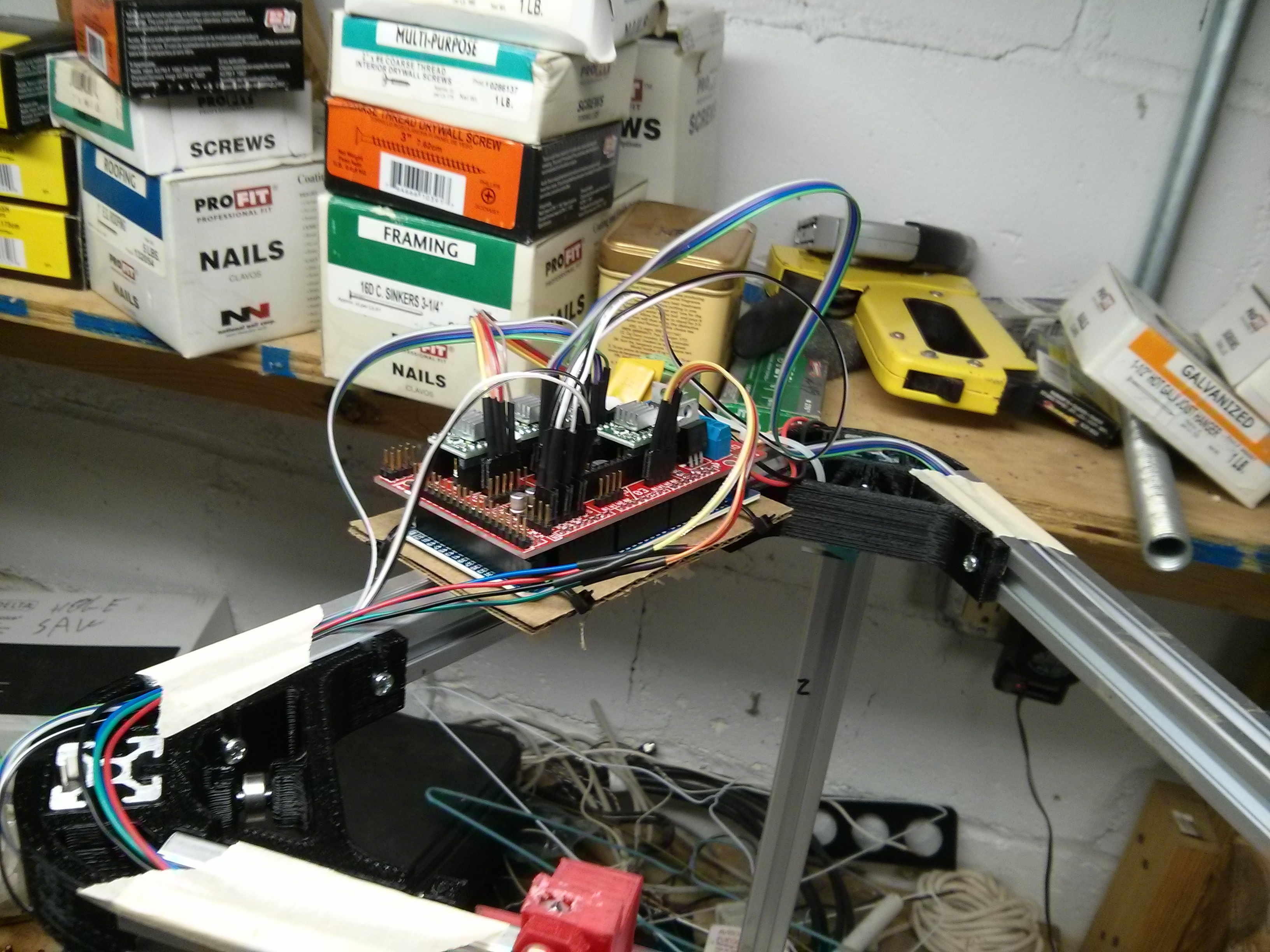
I decided that to make the cables neat, I needed to know ahead of time
exactly where the board would sit. The top seemed an obvious choice. So
I cut out a piece of cardboard just larger than the board, x-acto drilled
holes in it to zip-tie it to one of the top beams. Then I drilled more
holes to match the mounting holes on the arduino (the bottom board in the
sandwich), more zip-ties. Ta-da! Mounted.
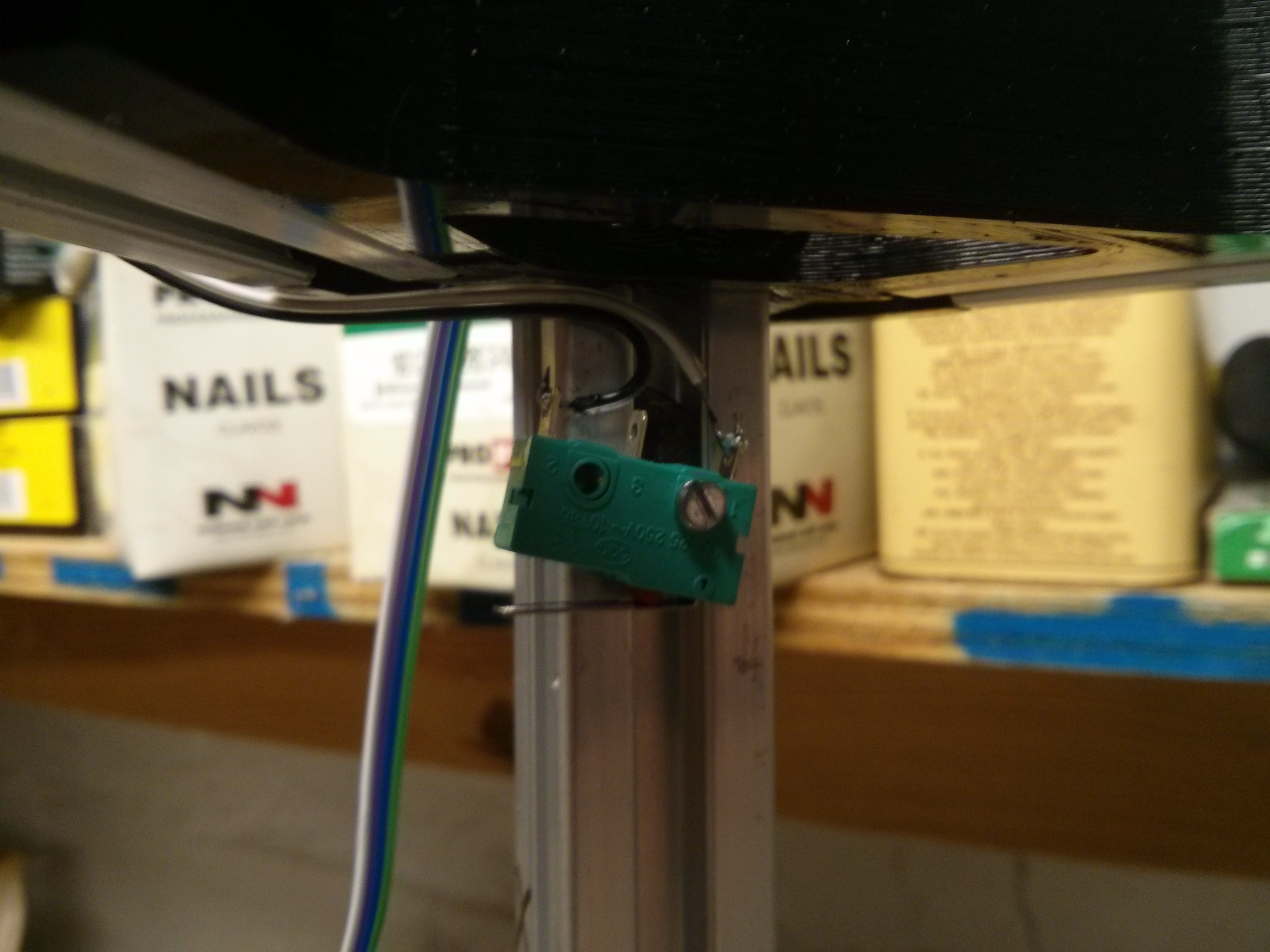
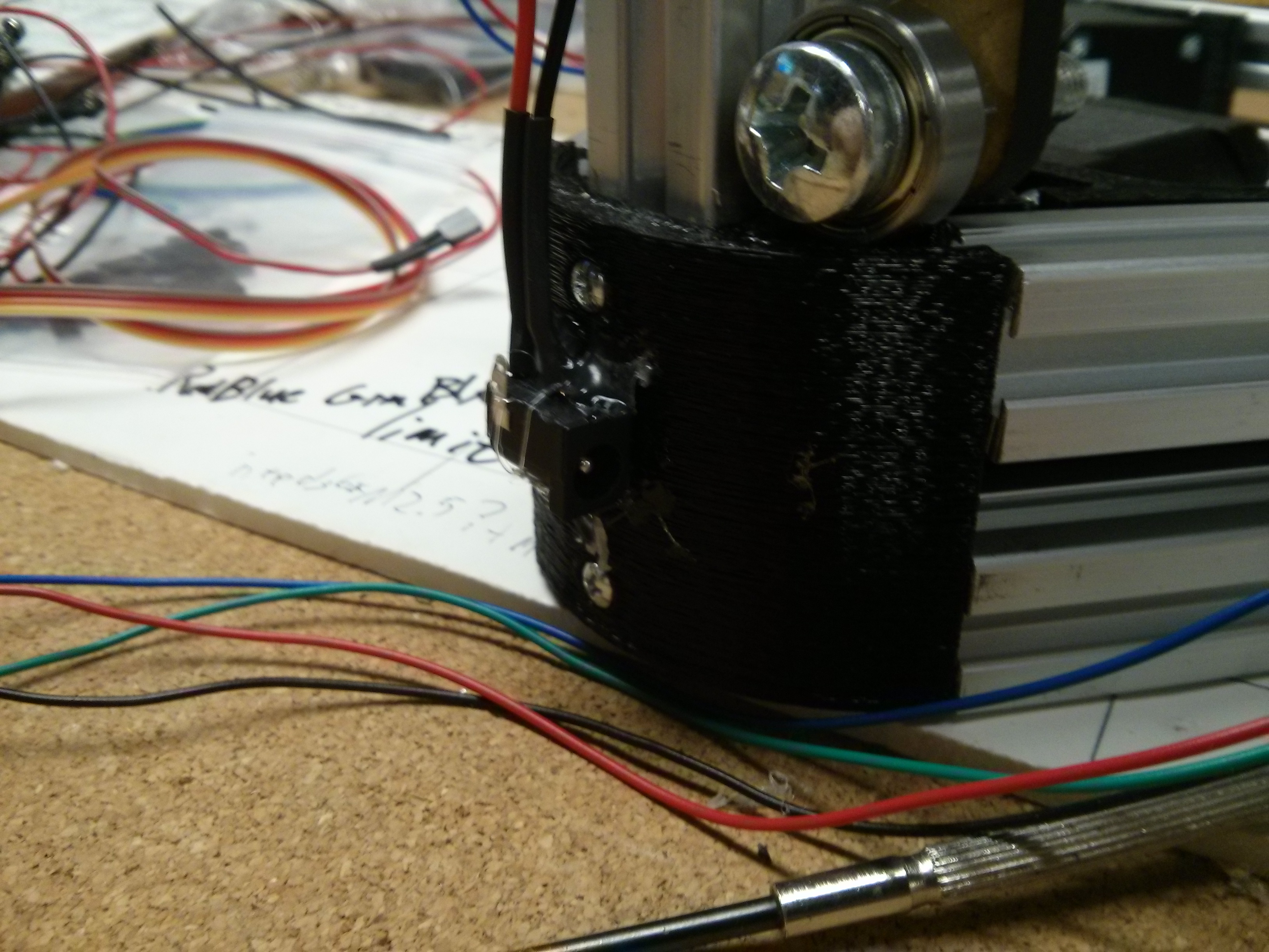
Then I peeled off two conductors from the ribbon cable in lengths
appropriate for the 3 limit switches. Make sure that you estimate based
on a neat path for the wires, rather than on straight-line distance. I
soldered them onto the switches, using the two outer pins of the switches as
Mixshop suggested. Then I tightened down the screw to lock it into a
final position. Make sure that the carriage cleanly triggers the
switch.
Similarly, I soldered lengths of 4-conductor ribbon cable onto the
tails coming out of all 4 stepper motors. Make sure to heatshrink these,
so they do not short out against the rails. Also, the order apparently
should be red/blue/green/black -- best to keep those in that order on the
ribbon cable.
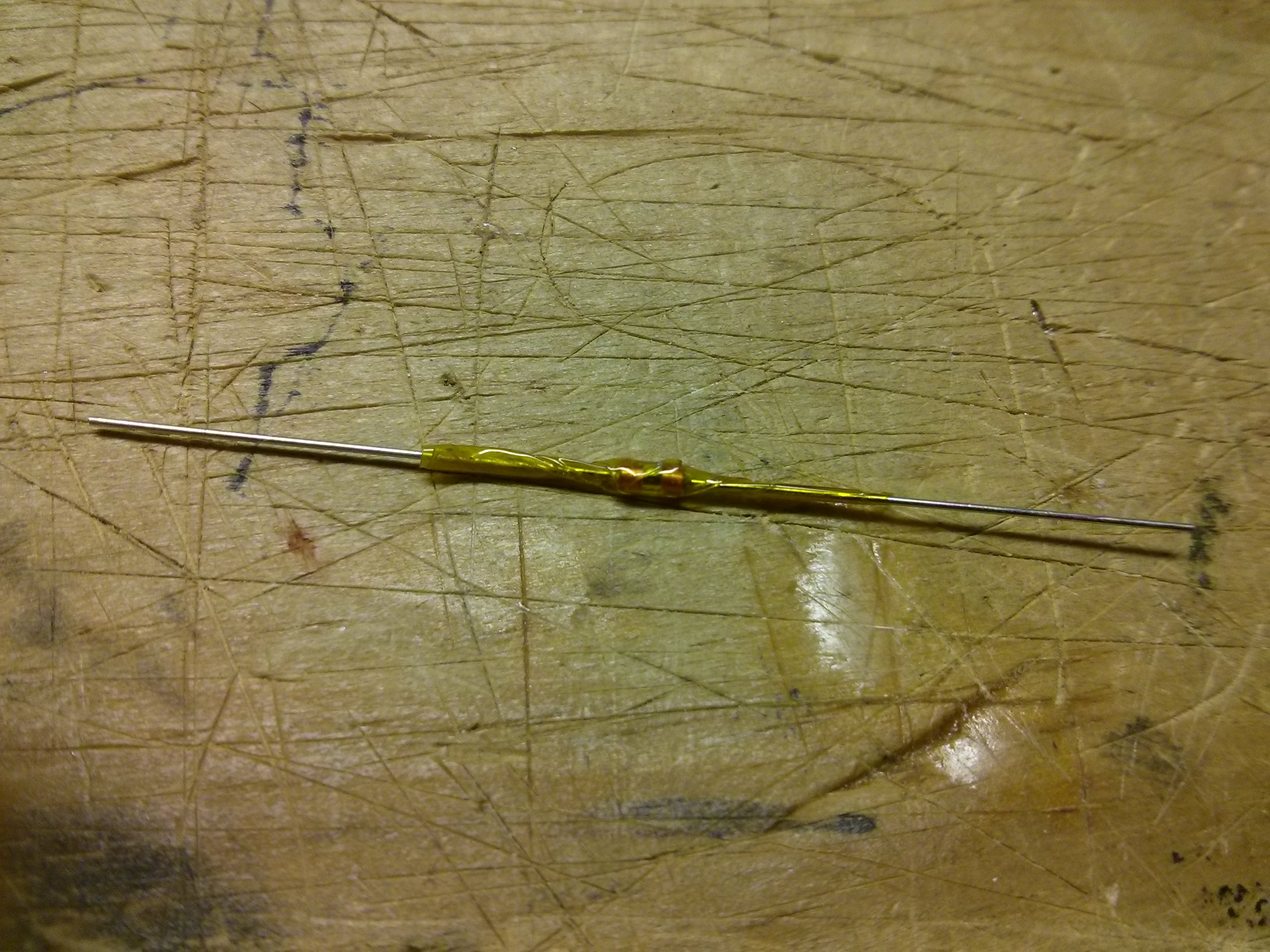
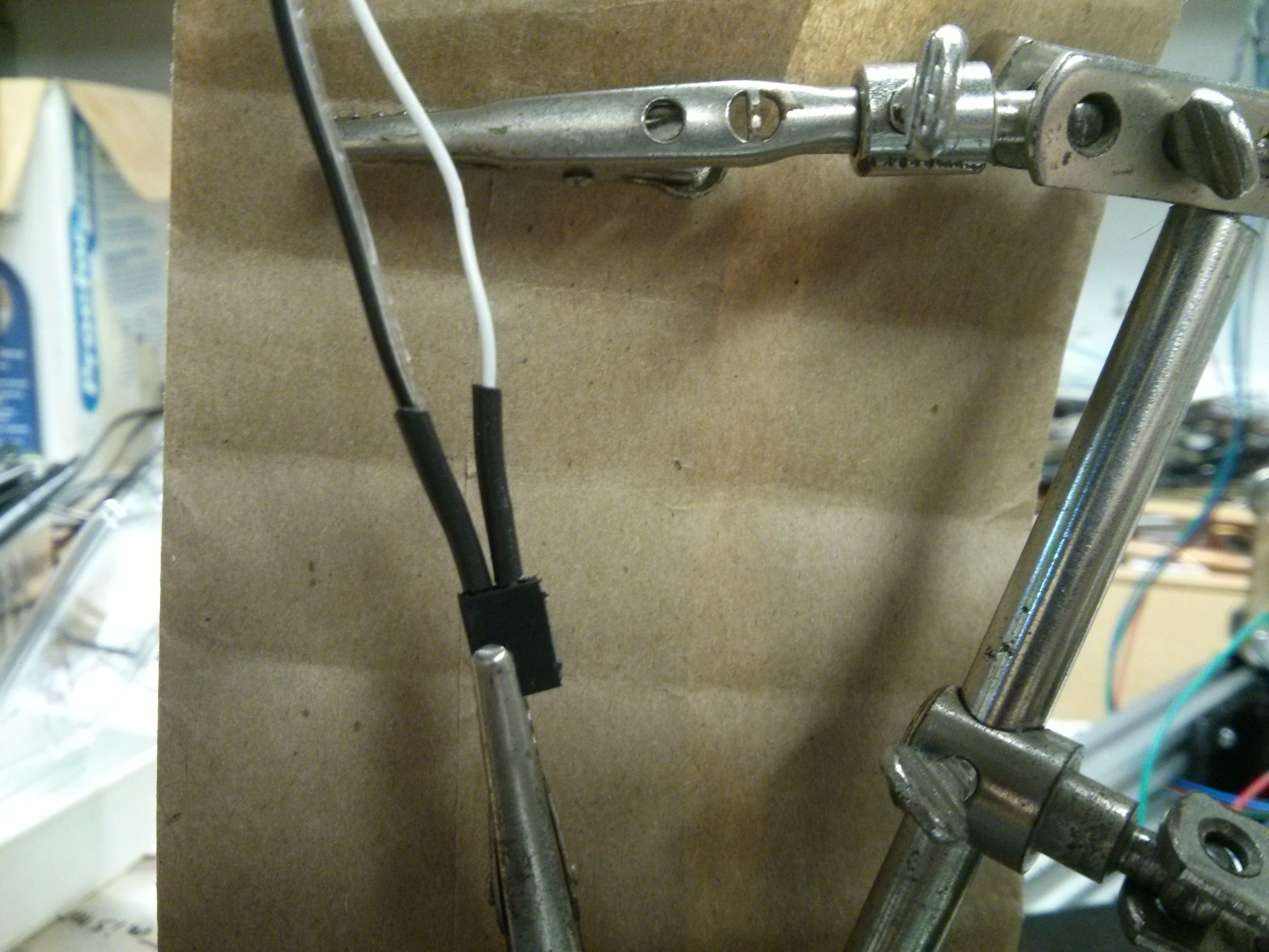
For the thermistor, it is recommended to use PTFE (teflon --
high-temperature) heat shrink tube around the thermistor both to ensure a
snug fit and to electrically insulate the leads from the heater block.
Regular (polyolefin) heat shrink tube will break down pretty rapidly at
printing temperature. I could not find any teflon heat shrink tube,
neither from the kit nor from a local store. Mixshop did, however, send
me a long roll of Kapton tape. So I wrapped Kapton long-wise (like
rolling a cigarette) around the thermistor:
Then I wrapped more Kapton around the leads where they would press
against the heater block, just to be sure.
Even without the Kapton, the hole in the heater block was slightly too small for the thermistor, so I bored it out with a drill press. I inserted the thermistor through the hole, and soldered 2 conductors of ribbon cable to its leads, and then put regular polyolefin heatshrink tube over the ends of the leads. Make sure you insert it before you solder it, because you cannot really do it the other way around.
Then onto the big resistor. Basically the same story. I wrapped the
leads (but not the body) in Kapton, and then added a little bit of
polyolefin heat shrink, really just to stabilize the Kapton.
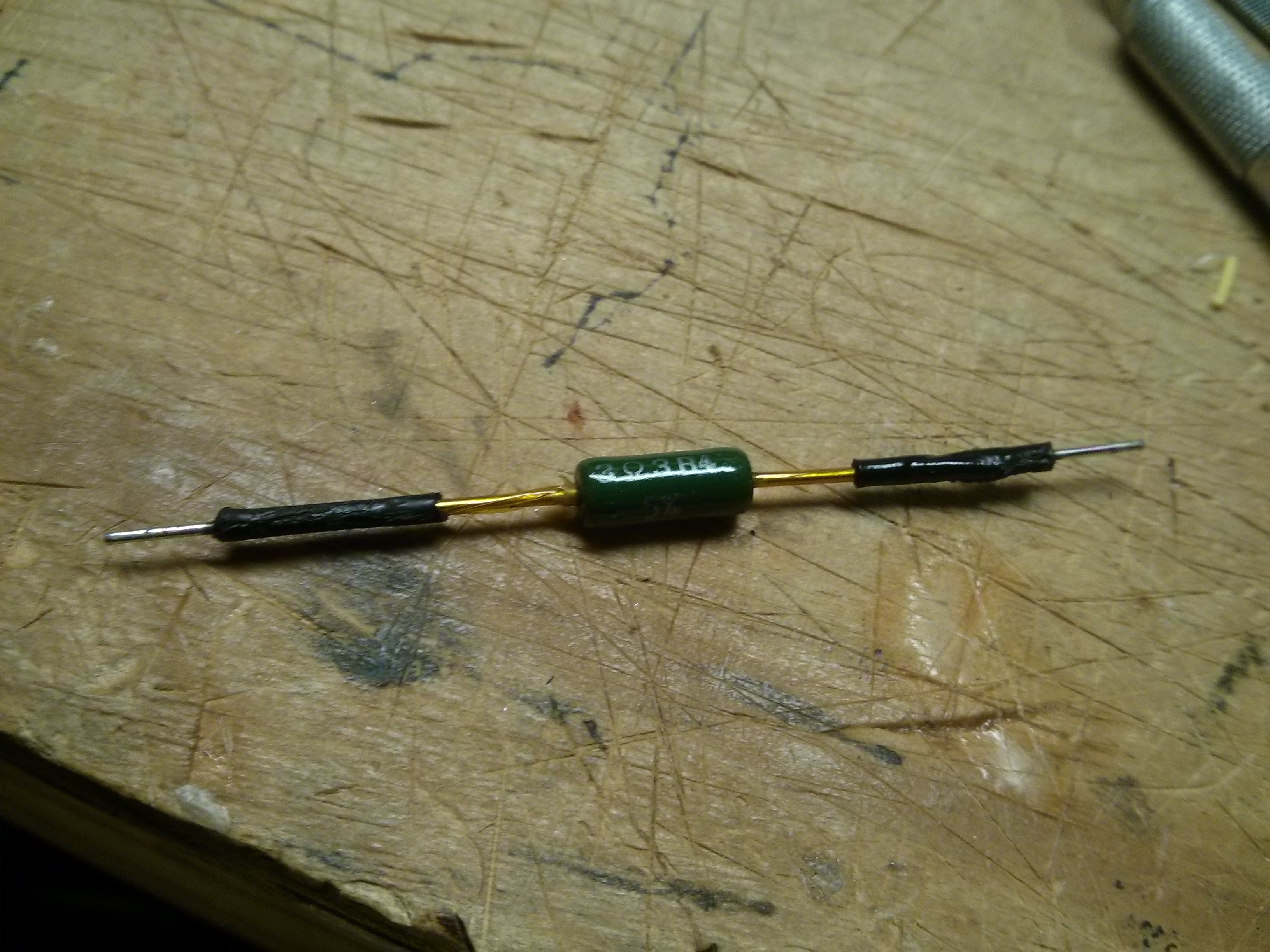
Bored out the hole (too much -- it's loose now *sigh*), inserted it.
This time I soldered it with a pair of the
thicker red-black wire because this will surely be a high-current
circuit. Because it was loose, I kind of went crazy wrapping Kapton
around it from different angles, to limit convection and to ensure it
won't move around much.
Then I soldered another 2 conductors of ribbon cable to the exposed connections on the probe switch.
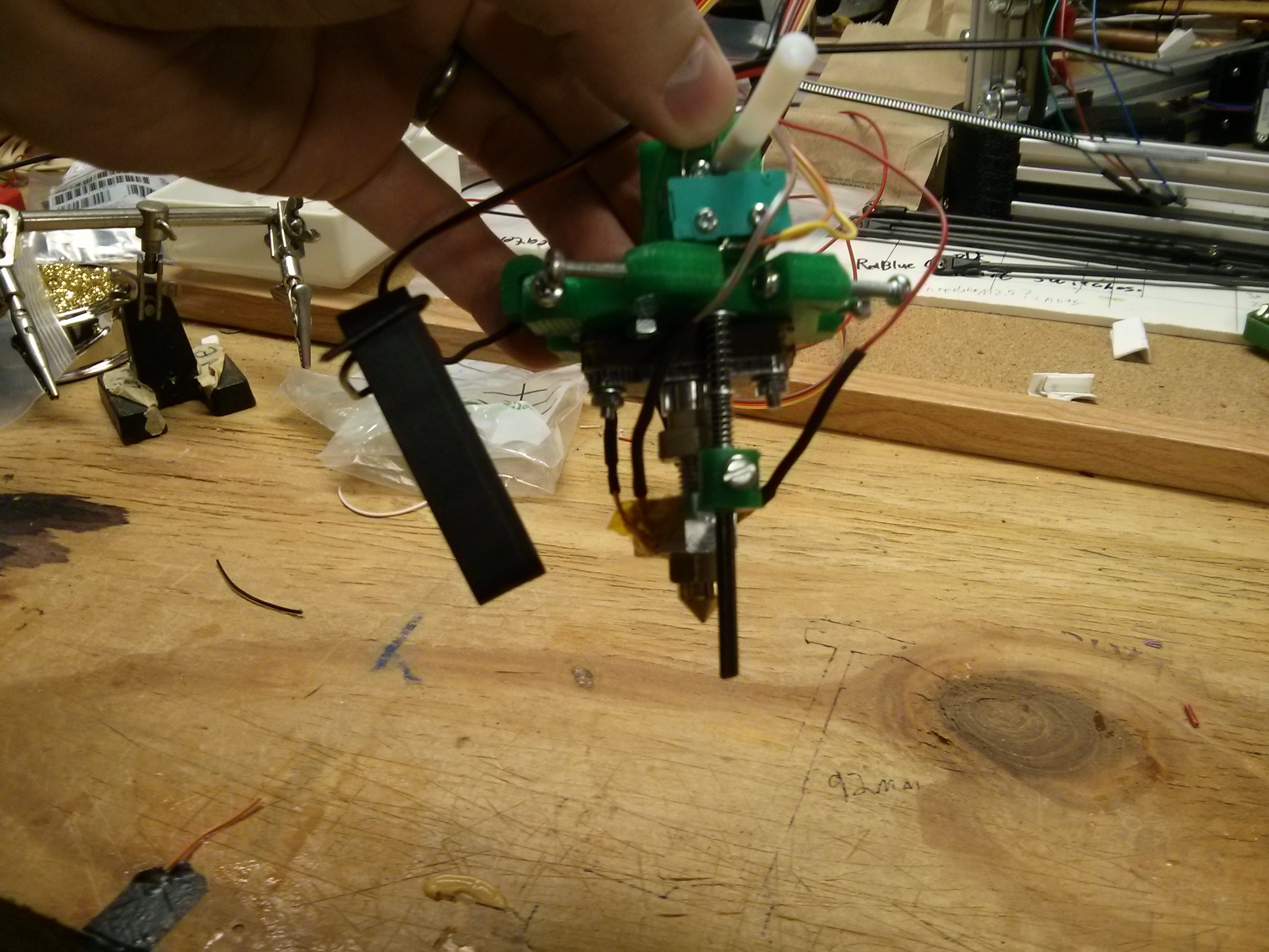
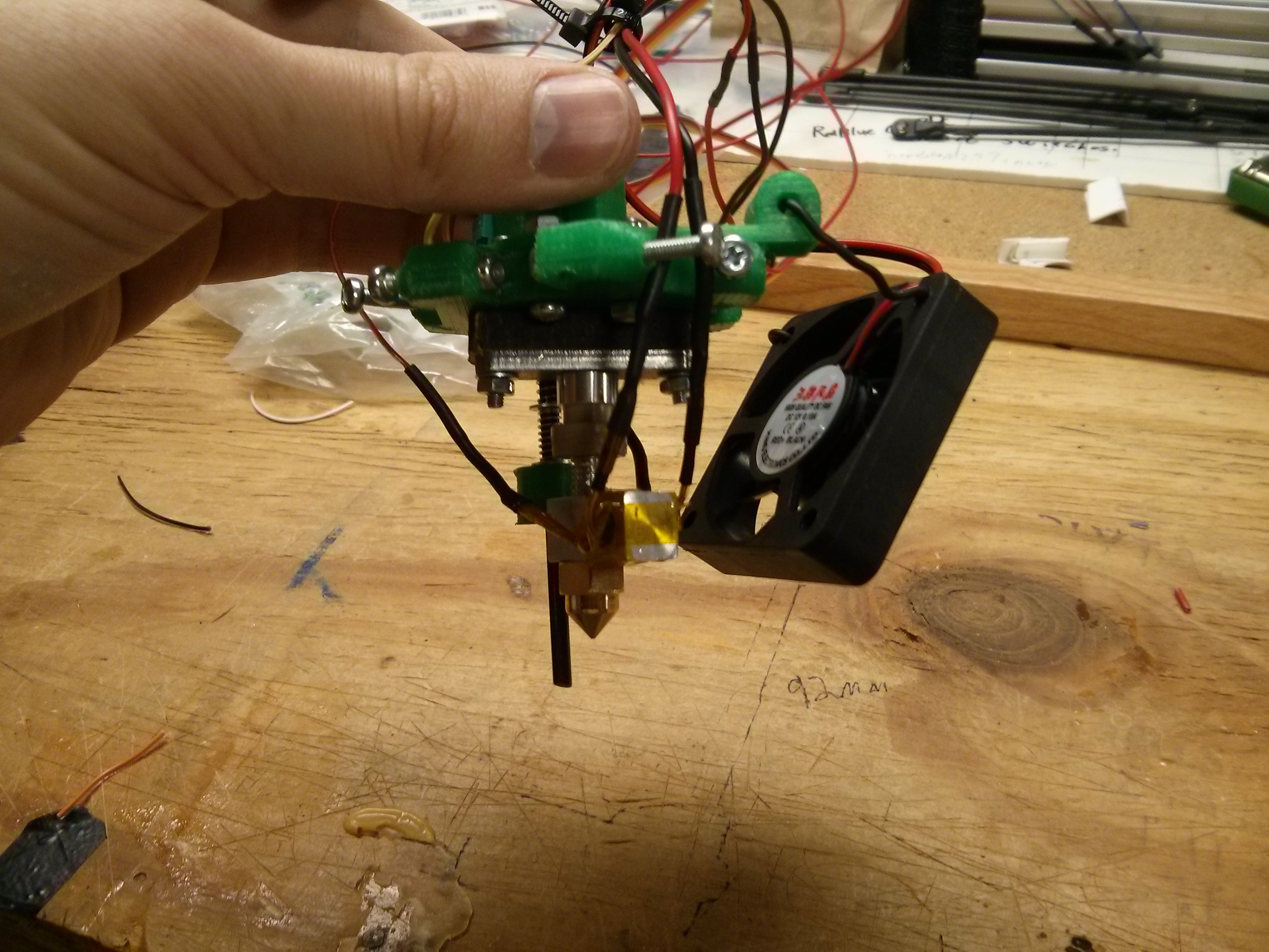
The final bit is the fan, which you want to have pointing at the top of the hot part (not at the nozzle). I couldn't figure out what Mixshop's intention was, so I simply bent up a bit of thick steel fence wire (ultimate paperclip) to hold it in position. I used the thick red-black wire again for the fan, because I was out of ribbon cable by this point. But I don't imagine the fan uses much current.
A quick zip-tie to hold the bundle of wires together for the moment,
and I'm done with the end effector.
Now for the fun part: all of the little 2-pin SIP connectors that go on
the end of the switch (and thermistor) wires (5 all together), and the 4x
4-pin connectors for the stepper motors. I could not find the
appropriate crimp tool locally, which was a real bummer. And soldering
on the included female connectors was not pleasing me. So I bought a
bunch of leaded female SIP connectors, and soldered onto those leads and
then added heatshrink:
Note that the fan and heater wires do not need to be terminated, as they ultimately go into screw terminals.
All that soldering is kind of a pain if your hands shake like mine do. Remember to tin the wires first! It makes it a lot faster so you don't melt the plastic connectors as much. And remember to slip on the heat shrink tube at the right moment.
Soldering sure does make a mess of your workbench...so many tools!
Now I think I'm done with most of the soldering and heatgunning, so I can put the belts on without fear. Something for later!
Now that I'm touching the electronics board, I want to collect some information resources.
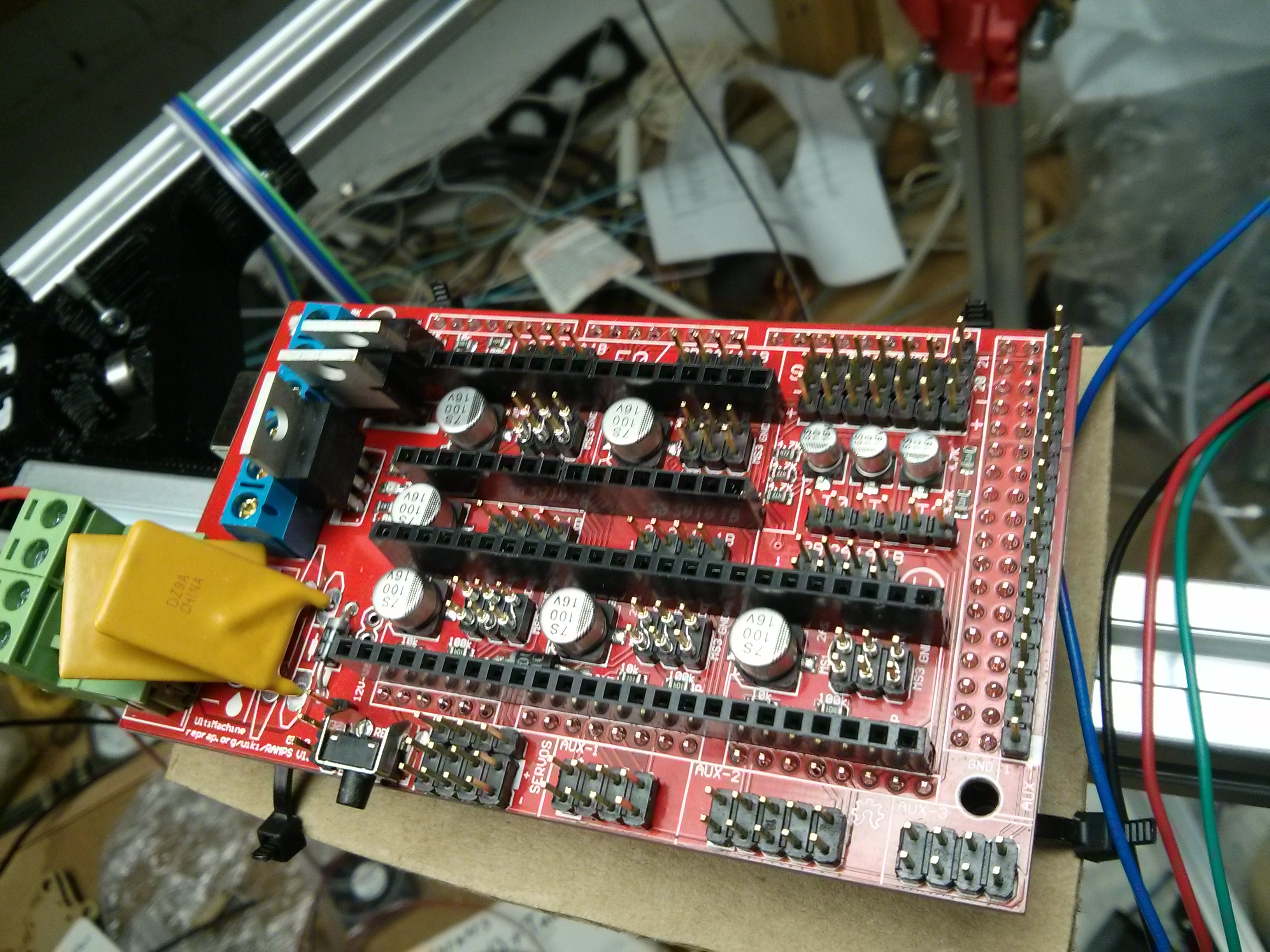
The RAMPS board is basically an I/O expander board. It has sockets for Allegro A4988 stepper motor drivers, which are packaged separately because they are the most expensive component on the board (so you can buy only as many as you need). Also, being up above the board like that makes them easier to cool. Apart from stepper motor drivers, it has sockets for switches, servos, I2C, high-current loads, a button (reset??), and more.
RAMPS stacks on top of an Arduino Mega 2560 (actually, it could be the 1280, I don't really know). That is a small single board computer based on an ATmega chip. It runs modified Marlin firmware (that's from Mixshop, though I think any Kossel firmware would be an acceptable start). It reads G-code over USB and sends the appropriate signals to RAMPS. Arduino is re-programmable so we can customize at will. It has only 8kB of SRAM, so it cannot store G-code, it must always be reading it from something (you can get an SDcard or Bluetooth module if USB is inconvenient on your workbench).
My first question: which board needs power? RAMPS needs
to be directly powered, and Arduino is capable of accepting power over
USB or from RAMPS. So just power RAMPS. Ignore the tempting barrel
connector on the Arduino. Mixshop included a loose barrel connector in
with the power supply, so I went
ahead and used it. I hot-melt-glued it to one of the bottom corners, so
that the power cable would not be arcing through the air to reach
RAMPS:
Next question: what about these jumpers in between the A4988 headers?
When installed, they pull high the A4988 MS1/MS2/MS3 pins, which are
basically a configuration option. When all three are high, that
asks the A4988 to do 16x micro-steps, which, you know, why wouldn't you?
It just makes the stepper motors more precise. Maybe a little slower?
Mixshop did not include any jumpers, so I wire-wrapped them.
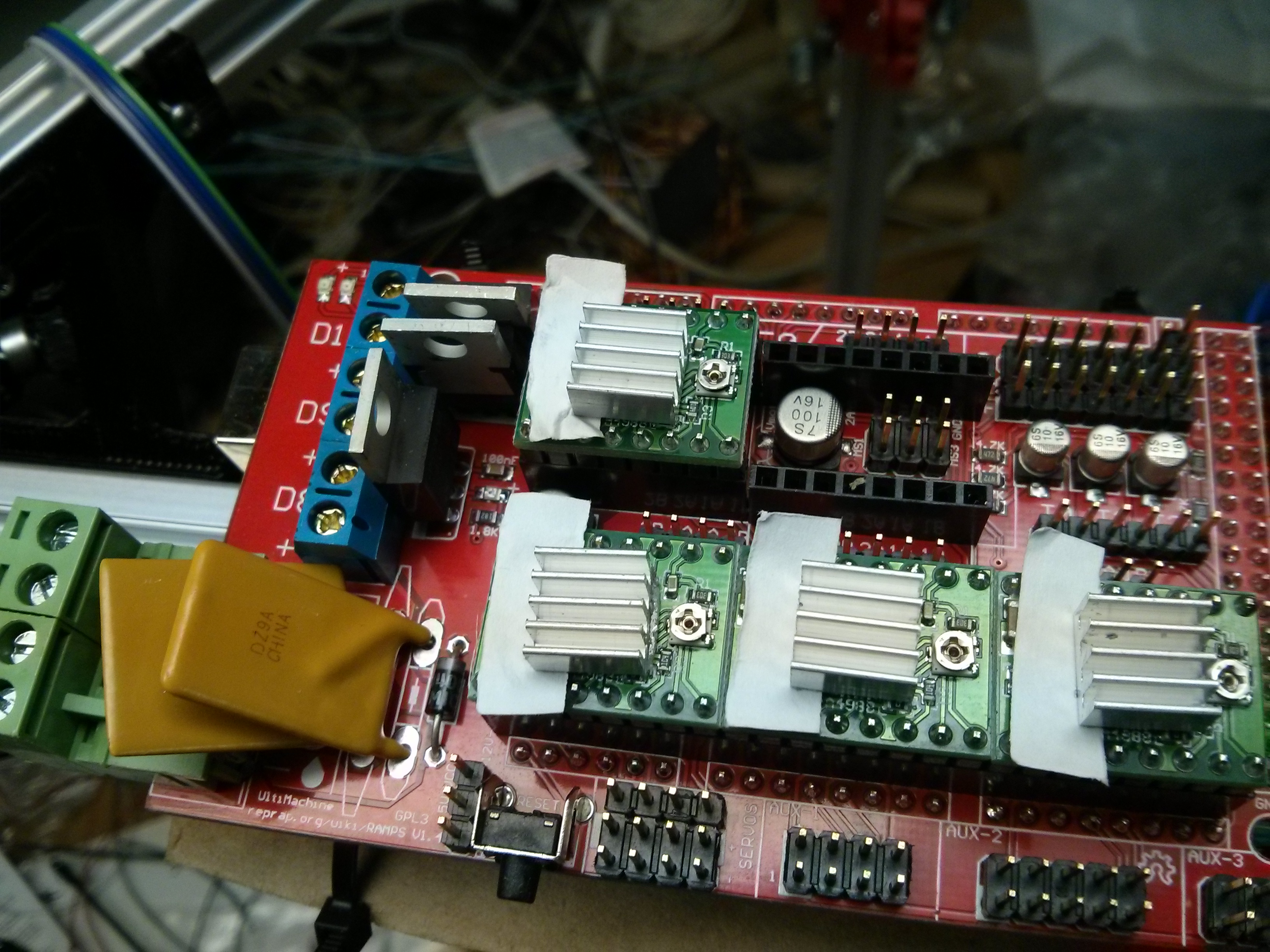
Then for the A4988 boards. The A4988 pins are labeled on the bottom,
so make sure to find those and verify the orientation before inserting
them. I installed the heatsinks with the double-sided tape already on
them. Make sure not to short them against the pins. In an abundance of
paranoia, I inserted a piece of paper between the heatsink and some
surface mount components that seemed uncomfortably close.
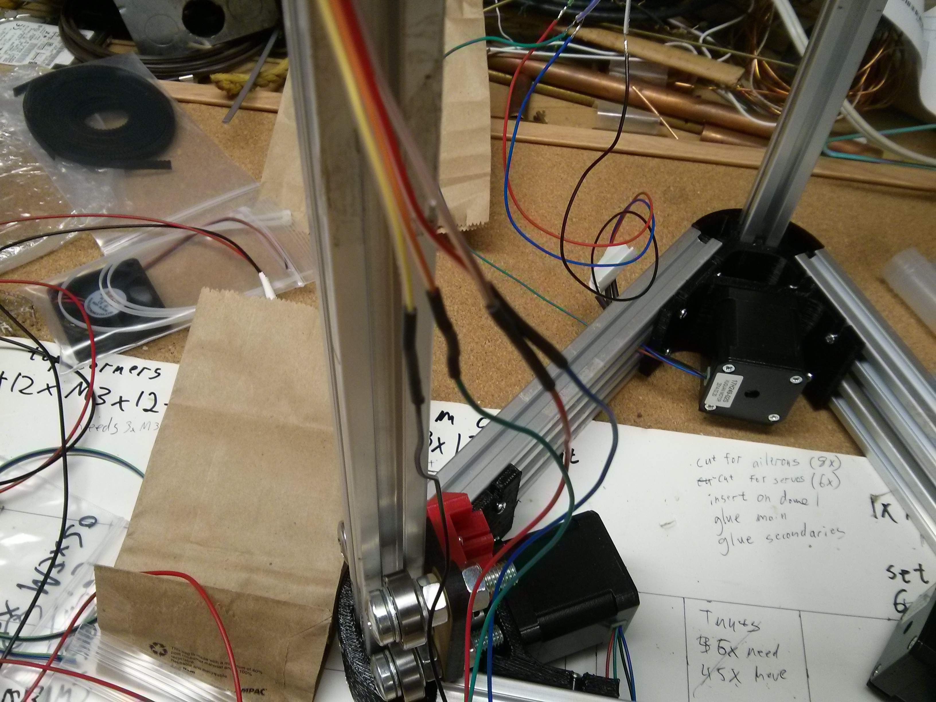
Now I plugged in all the wires that are on the frame -- stepper
motors, limit switches, and power. To determine which column was X/Y/Z,
I started with X on one and then proceeded counter-clockwise (looking
down from the top). I used bits of tape to encourage the wires to run
through the channels in the beams to keep everything relatively
neat.
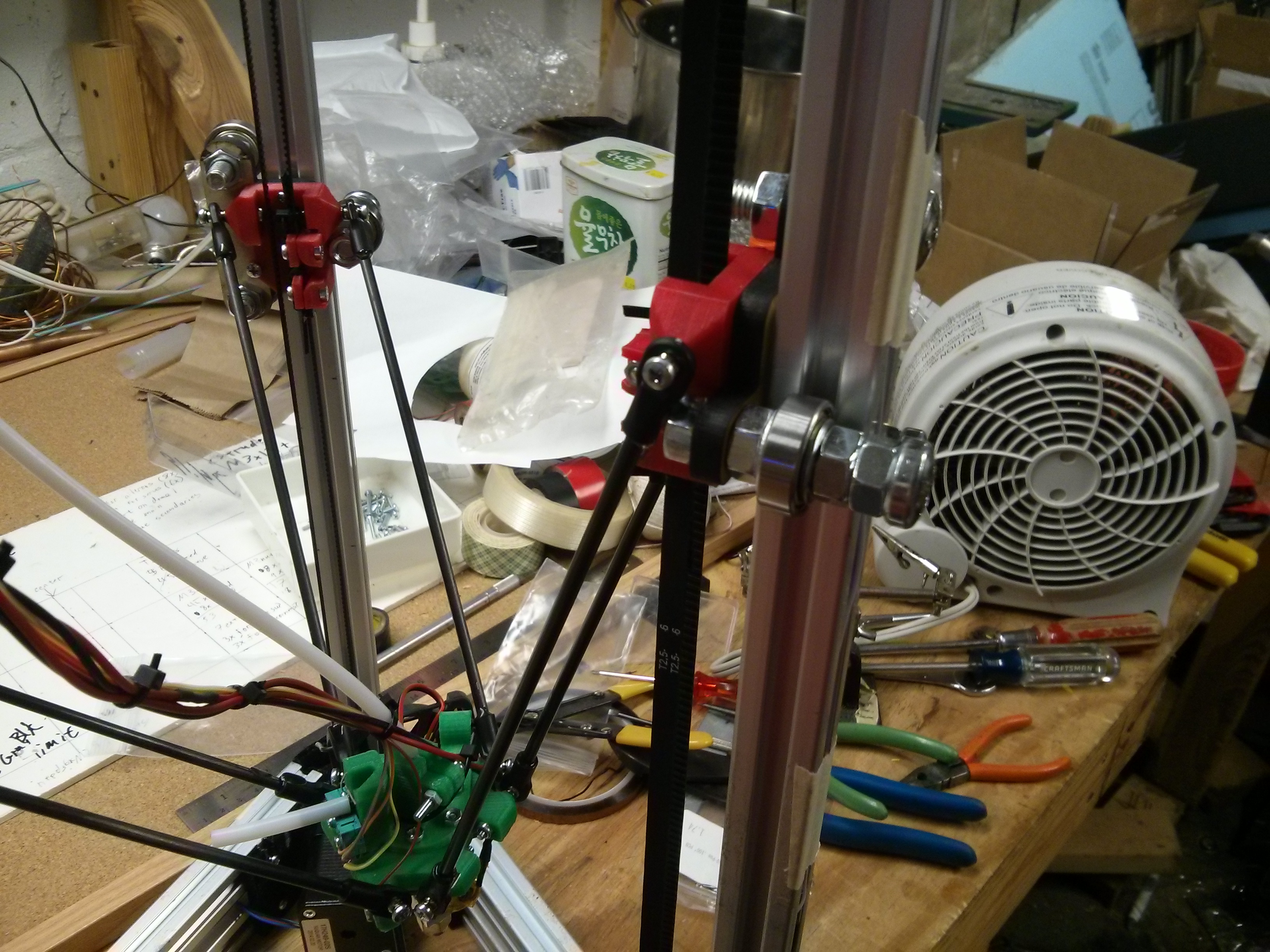
So it is time to attach the belts and rods, now that I am fairly confident I won't need to be waving a soldering iron or heat gun at the machine anymore.
Attaching the 6 rods to the end effector went without incident. I used 6x M3 nyloc nuts, and 6x M3x25. I could not use the included M3x20s because they could barely reach into the nut and would not engage the nylon locking threads at all. But if I had not used the nyloc, it seems like M3x20 would have sufficed. It sure is awkward to handle the end effector with 6 rods hanging off of it! I kept on expecting to hear the sound of carbon fiber cracking as it jams against someting.
Attaching the rods to the carriages was a minor nightmare. First, I
noticed that using an M3x25 on the left side causes interference with the
moving belt, so I used M3x20 on that side to avoid that. I'm not sure if
it really engaged the nyloc threads or not -- it is close. But on the
other side, I still used an M3x25 because the interference with the fixed
belt didn't bother me any. So a total of 3x M3x20, 3x M3x25, and 6x M3
nyloc nuts.
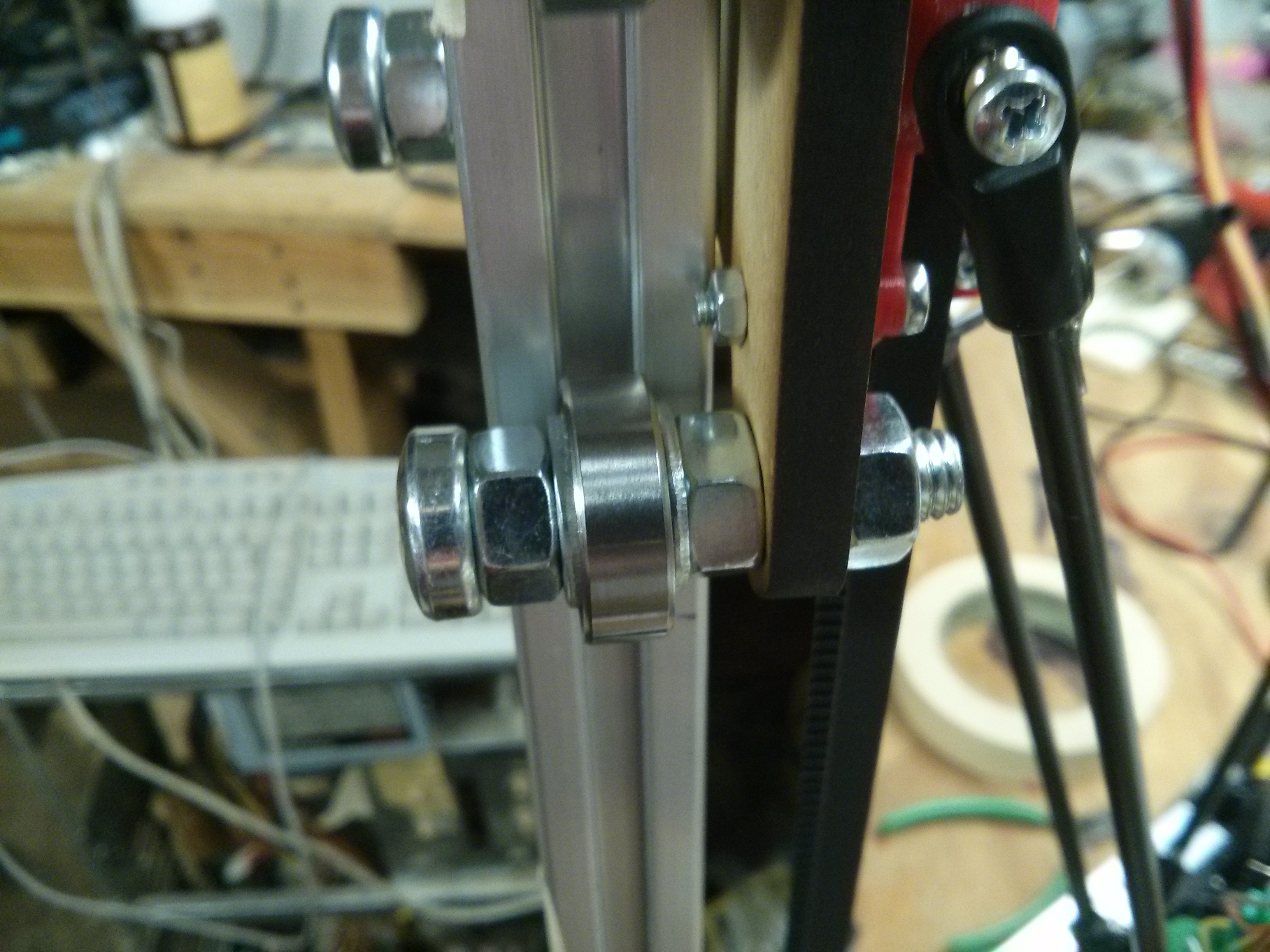
The next thing I noticed once I got a rod onto it is that the end of
one of the M8 bolts dramatically interferes with one of the rods! It
severely limits the print radius. I think that's because Mixshop
switched to using longer bolts at the last moment -- the build manual
shows much shorter ones. Anyways, I put two of the extra M8 nuts on
each carriage to use up bolt length so that it would not stick out of the
final nut:
Then I noticed that a bolt interferes with the other rod too. It is
not nearly as severe, but I solved it with one extra M8 nut on each
carriage:
I pulled the belt through the slots, and pulled about as hard as I dared to to get it pretty tight. I tightened the tension screws. One of them caused an obvious bit of plastic to snap, but at least for the moment it is still hanging onto the belt. I think it is only a trouble because the bending goes against the grain of the print. I used zip ties to keep the excess belt out of the way, rather than cutting it off.
Then I installed the PTFE tube. I only got it about a quarter inch
into the hole on the top of the end effector, so when I put it in the
extruder, I went crazy with the heat gun on it. I went too far! But it
still holds on just fine.
Then I zip-tied the cables coming off of the end effector, so that
they wouldn't snag and tangle as it moves.
I also zip-tied the top of the cable to the frame so it wouldn't flex right at the connectors, and then attached the end effector wires to the RAMPS board (heater, fan, depth probe, and thermistor). I tested the resistance of the thermistor (113kOhm -- seems high? Need to make sure Marlin is seeing a sane temperature before powering up the hot end), and the heater resistor (about 4.5 Ohm -- my meter is not good around 0). That resistor seems like it would draw around 3A at 12V, which is a lot, but I guess that's what it's there for! At least neither of them were shorted with the heater block.
Even without any bolt poking out the end, one of the M8 nuts
on the carriage still interferes!
It's not a very severe interference so far as usable print radius goes.
I can still move the end effector far enough that the fan interferes with
the belts (maybe I should move the fan, though). When I move the end
effector to the position where it deploys the depth probe (by running the
PTFE tube on it against the belt), the rod contacts this bolt! It
doesn't add much resistance to keep going after contacting the bolt, but
it does flex and stress a few things (the rod and the plastic part of the
carriage, at least). Highly un-ideal!
That is pretty vexing. To solve it, I will either print my own carriages with a slightly different design (maybe four rollers per carriage instead of three?). Or I will print my own plastic part of the carriage that is just a little bit thicker (holds the rods further from the wooden part). Or I may just insert some shims between the existing plastic and wooden parts. I'm definitely not happy ramming the rod against that nut every time I calibrate the printer, and I might appreciate the slightly larger build radius too.
Anyways, it's assembled now!
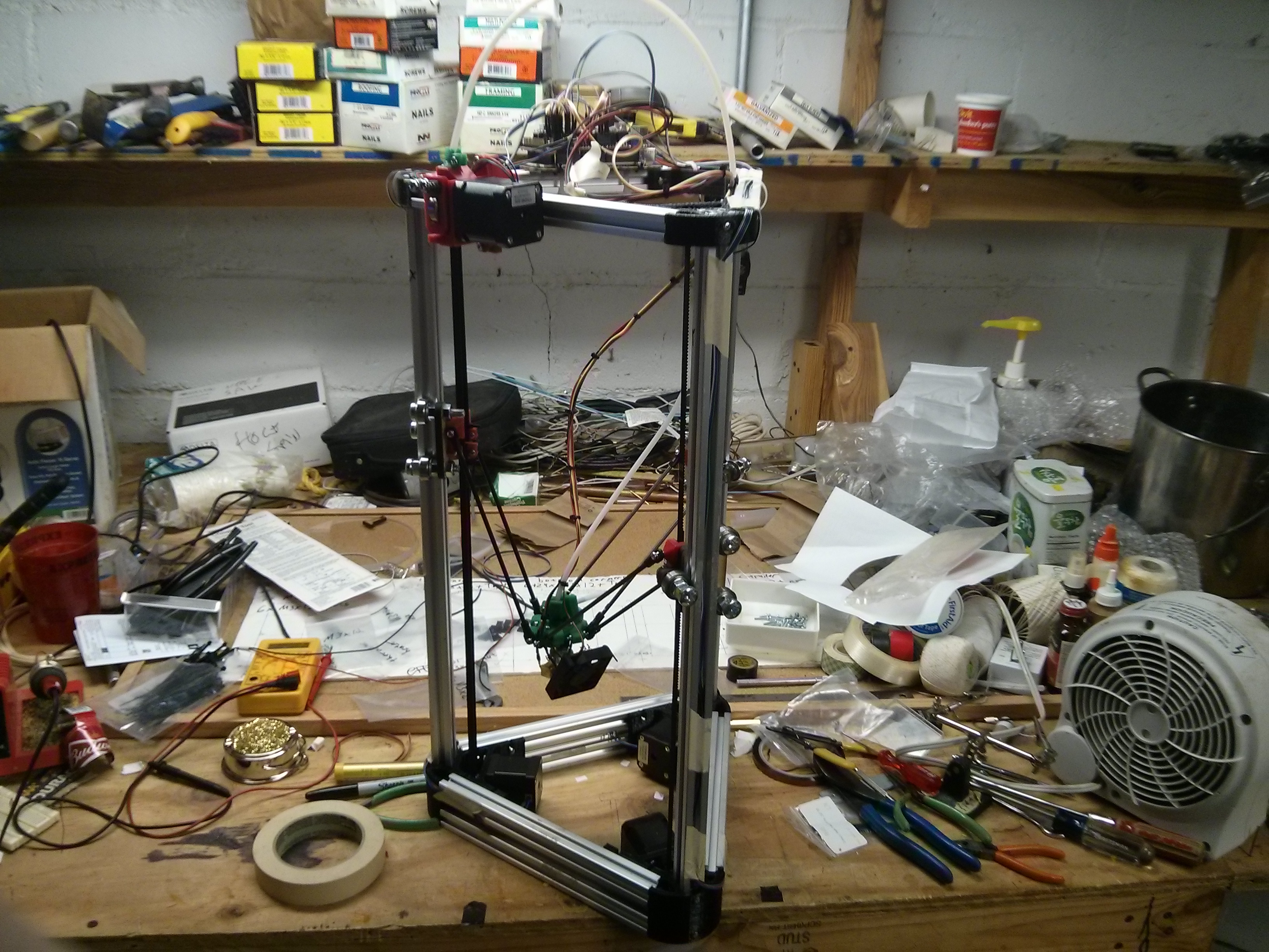
I cannot use the little laser-cut piece of wood that is supposed to fix the position of the plexiglas/acrylic build platform, because I do not have any more of those proprietary T-nuts that lock to the beams. I may have to print some of those (I think I can make one that works the same that traps a regular M3 nut). I think that the wood positioner is a joke anyways.
One of the things I love about Kossel/delta design is that your print platform can be a joke. It seems like the build platform might be somewhat smaller than our usable radius, but I'm not entirely sure about that. But I might replace the platform with glass anyways, especially if I manage to damage the acrylic.
I haven't used the second fan. I've seen it suggested to have a fan on the end effector pointing at the work (pointing below the nozzle), which makes sense to me. I've also seen it suggested that the fan should point at the extruder stepper motor -- I don't see how that makes any sense though. And the stepper motor drivers on the RAMPS board might overheat, which would necessitate a fan up there. So I'll just hang onto it for the moment.
This is actually the least fun part for me. I do not know what I am doing, I can't print yet, and I have built it enough that if I break it I'll be sad.
I am not crazy about how the reprap community is largely the same as the smartphone community in terms of their sophistication as open source developers. That is to say, source management skills are lacking. People just hack onto whatever they happened to get, and don't give any thoughts to merging or upstream commits or any of that. In other words the code is just a means to an ends, and there are few dedicated programmers involved.
C'est la vie. I compromised by downloading the jcrocholl's delta-modified Marlin from github. I prefer it to the firmware from Mixshop merely because it is less-ambiguously maintained and because I think I can figure out how to submit patches if I come up with any. The downside, of course, is that I may be the first to use it with this Mixshop kit.
I wanted to avoid any IDEs or big host packages, so I ran apt-get install gcc-avr avr-libc avrdude on my Debian (Linux) machine. Unfortunately, even though Marlin comes with a Makefile, it seems to depend on some header files that are only available with the Arduino dev kit, so I downloaded version 1.0.5 of that from arduino.cc.
Here are the changes I made to the Makefile:
And I had to remove a #include <time.h> from qr_solve.cpp. I don't know what it was doing there -- there is no time.h on Arduino as near as I can tell, and it apparently wasn't necessary.
And here are the changes I made to Configuration.h:
#define X_PROBE_OFFSET_FROM_EXTRUDER 1.5
#define Y_PROBE_OFFSET_FROM_EXTRUDER 12.5
#define Z_PROBE_OFFSET_FROM_EXTRUDER -8.0
- the X axis is the direction between the X and Y towers (right is +X, back is +Y), and I just measured based on that
Then I built it with make, and attached the USB cable and uploaded it to the Arduino board with
I noticed that the verification step fails about half the time, I guess due to poor quality serial link between the FTDI and ATmega or something. Anyways, if you want to just repeat the verification without waiting for the write again, try:avrdude -D -p atmega2560 -P /dev/ttyACM0 -c wiring \ -b 115200 -U flash:w:applet/Marlin.hex:i
avrdude -D -p atmega2560 -P /dev/ttyACM0 -c wiring \
   -b 115200 -U flash:v:applet/Marlin.hex:i
Then I connected to it with minicom, a Linux terminal emulator that I haven't used since like 2002. Aside from setting up the port, I also had to go into configure minicom -> screen and keyboard and enable "Local echo", "Line wrap", and "Add carriage return". When it connects, this is what the Arduino says to me:
start
echo: External Reset
Marlin1.0.0
echo: Last Updated: Apr  4 2014 23:55:32 | Author: (jcrocholl, Mini Kossel)
Compiled: Apr  4 2014
echo: Free Memory: 1507  PlannerBufferBytes: 4928
echo:Hardcoded Default Settings Loaded
echo:Steps per unit:
echo:  M92 X106.67 Y106.67 Z106.67 E100.00
echo:Maximum feedrates (mm/s):
echo:  M203 X200.00 Y200.00 Z200.00 E200.00
echo:Maximum Acceleration (mm/s2):
echo:  M201 X9000 Y9000 Z9000 E9000
echo:Acceleration: S=acceleration, T=retract acceleration
echo:  M204 S3000.00 T3000.00
echo:Advanced variables: S=Min feedrate (mm/s), T=Min travel feedrate (mm/s), B=
minimum segment time (ms), X=maximum XY jerk (mm/s),  Z=maximum Z jerk (mm/s),
E=maximum E jerk (mm/s)
echo:  M205 S0.00 T0.00 B20000 X20.00 Z20.00 E20.00
echo:Home offset (mm):
echo:  M206 X0.00 Y0.00 Z0.00
echo:Endstop adjustement (mm):
echo:  M666 X0.00 Y0.00 Z0.00
echo:PID settings:
echo:   M301 P22.20 I1.08 D114.00
I guess I had a burst of impatience, because I plugged in the main 12V power to the RAMPS board, and typed G28 - which should home it at the top-center. The motors started to spin, and the end effector was descending! It hit the print bed before I could turn it off!
I had read about this problem, so I changed X/Y/Z_HOME_DIR from 1 to -1 and tried again. Same thing! I let it hit again! Ack! I could cry! One of the belts is loose now -- did it stretch or did something slip? Oh no!
So I dug into the source, and it turns out -- at least for this firmware -- X/Y/Z_HOME_DIR are largely ignored, or at least do not influence the direction the motors turn. Anyways, they were correct at 1. So what I did is I simply turned the SIP connectors for the X/Y/Z stepper motors around, and plugged them back in. I would guess that maybe I built my carriages as the mirror image of how Mixshop meant them, and that's why their wiring directions didn't do me quite right on the first try -- but it's easy enough to turn them around!
This time I was more cautious. I issued M119 to read the limit switches:
M119
Reporting endstop status
x_max: open
y_max: open
z_min: TRIGGERED
z_max: open
z_min (the depth probe) was triggered because the PTFE tube on the end of the hex wrench had started to slip off and no longer touched the switch appropriately. I put a little hot melt glue to hold that in position. Then I repeated M119, holding each switch one at a time to make sure it was reported correctly.
While I'm being cautious, let's check the thermistor with M105:
M105
ok T:19.7 /0.0 B:0.0 /0.0 T0:19.7 /0.0 @:0 B@:0
19.7C is 67.5F, which is a pretty accurate measurement of my basement's ambient temperature. I touched it for a little while and it went up to 21.2C. Yay!
Now G28 again, and it worked! It brought it up nice and neat to the top-center position!
M106 S255 turns on the fan, M106 S0 turns it off.
Hotend test. M109 S50 - set it to 50C, which is hot but not dangerously so. It shoots up to 50C in only about 30 seconds, but then it overshoots to 70C and takes minutes to come back down. Once it got to the right temperature, it is holding 50C very well. This "PID" stuff everyone talks about is some sort of complicated feedback loop to try to maintain a steady temperature. I guess it might need some tweaking, but on the other hand overshoot when aiming for 50C is hardly a big deal (since it usually operates closer to 200C).
Now I did M109 S60, which corresponds to 140F which is exactly the threshhold of scalding (the target temperature for many hot water heaters), which I should recognize pretty easily with my fingertip. Again, it overshoots, but this time only to 69C. Once it was at 60C, I turned the fan on, and it dropped briefly to 58C and recovered quickly.
Now to test the extruder. M302 to allow cold extrusion (I haven't got any filament in it), then G0 E10. No effect. Maybe it won't extrude unless it's moving too? I tried G0 Z200 E10 and that didn't turn the extruder either. Maybe M302 only disables the error message, but still extrusion is disabled unless the hot end is up to temp?
I am carefully testing basic movement, first G0 Z20, it is about 2cm above the print bed, I can hold a ruler here easily. G0 X20 and so on, walking around 2cm off the print bed. It is moving in a fairly level plane (the print-head is about 1mm higher around the edges of the print area, as near as I can tell), and it is moving the correct distance as well as I can tell with my ruler. So I must have calibrated it decently well just in Configuration.h.
One thing I notice is that G28 is not super reliable about moving all 3 towers up at the same time -- sometimes one of the towers won't move at all for a moment. This is bad because it can put the arms in all sorts of funny configurations. I notice that homing is much faster than moving around (moving around seems reliable), so I would speculate that the stepper driver is stalling out, either because it hits an overheat cutoff or because its current-limiting trim-pot is set too low. For now, I think I will just reduce the homing speed.
It would be nice to be able to use G29, but for the moment I am terrified of it. The first step to deploy the probe is scary (it might ram the arm against the bolt that interferes with it), and the last step to retract the probe is scary (god knows where that spot is). I'm going to try to avoid using G29 too often, because I don't trust the cleverness of this probe design.
Another thing I noticed is that the A4988s do get a little bit warm, and when they do, the sticky tape that holds the heatsink on gets soft! I really did not imagine there would be such a poor compound used on heatsinks, but apparently this is a common complaint with these little heatsinks. Anyways, apparently putting a heatsink on top of a chip like this is stupid anyways, so I just pried them off. If they overheat, I'll install a fan.
Here is a handy reference of the G-code commands for interactive testing:
I have been afraid of the stalling stepper motor problem because if the stepper motors are not just absolutely reliable then it will surely become miscalibrated as it runs.
I skimmed RepRap Calibration wiki, and it gave me a good feel for what I need to accomplish with the stepper motors, even though it is intended for non-delta printers.
I discovered G0 Ffff, which sets the feed rate (x/y/z movement rate) in mm/min. I've seen extreme videos of 250mm/s, or F15000. I tried that with my printer and the motors did not spin, just buzz. I tried F12000 (200mm/s), and they moved but not reliably (if it traced a square, it didn't return to the same spot at the end). I tried F10000 (167mm/s), and that seemed rock-solid. In particular even after I had it trace a bunch of squares in the air, when I had it return to 1mm below the top limit switches, it did not trigger them...and when I had it return to 0mm below them, it triggered all of them simultaneously. Repeatability!
Anyways, I noticed it still sometimes behaved poorly in G28, so I started fiddling with the potentiometers on the driver boards. They were pointing at what I would call 6 o'clock (flat side directly opposite the IC chip). I had to turn it way low, to about 1 o'clock to get it to stall out. A little higher and now it runs, and then I just pushed it a little higher than the minimum to get it to run, and now it is at 3 o'clock. Which is about where some guides suggested, as I recall. So that is substantially less than before, which seems good.
Now F15000 can turn the motors, but F12000 is still unreliable and F10000 is still reliable. 166mm/s is plenty fast for me, no need to push the limits, so I am not concerned about it.
While I was playing with this, one of the Traxxas ends came off of the rod! I think it had been repeatedly bashed against one of the things that interferes with it, and it had cracked the epoxy. I just shoved it back on, and the ring of old epoxy provides a gauge to make sure it goes in the right spot. We'll see if it comes apart again *sigh*. That makes me really nervous about the delta design, because any number of incidents during printing could cause that to happen.
Another thing that is not so clever, I guess really a flaw in the Marlin delta firmware, is that G0 X50 Y0 at the top (say, just after homing) will cause the Y tower to ram powerfully against its end stop! Delta geometry obviously doesn't allow you to be off-center at the top, but the firmware doesn't do anything to prevent you from trying. I tried G0 S1, which is supposed to make it honor endstops, but it still kept pushing (maybe it has to be specified on each movement command, which would be lame).
I really fear that I am stretching these belts out, though holding a ruler against them doesn't show any stretch. I guess I just need to tighten them back up where they attach to the carriages.
Also, I was all set to learn some math to calibrate the thermal PID settings, but I found RepRap PID Tuning wiki. It turns out it is as simple as M303 E0 S200 C8, which generates some values you can put in Configuration.h.
And last but not least, I wrote send.pl, a perl program to send commands to the printer. To run it, you will probably need to install Device::SerialPort from CPAN. As root run perl -MCPAN -e shell then install Device::SerialPort. The port settings are in variables at the top of the file.
I found send.py and RepRapArduinoSerialSender.py, but it had a few infelicities:
Anyways, no one ever uses these sorts of programs, I'm sure most people let their G-code generation program talk directly to the printer. *shrug*
So with any luck I might actually print something with this before I destroy it.
I installed Skeinforge, but its configuration was poor. I know there are only 5 things I want to configure at first, and only 25 after that, but it has everything scattered through numerous cryptic panes. I thought it would be more command-liney, but in fact it is just less organized. Oh well.
I installed Slic3r, and it immediately asked me for the 5 things I knew I wanted to tell it. I figure that is a good sign. Back to calibration...
I calibrated the extruder. I measured the hob diameter about 8mm. Times pi gets circumference: 25.1mm. It's 3200 steps per rotation (200*16), so 127.5 steps/mm (3200/25.1). I loaded it up and asked it to send 50mm through the tube, and it looks like 50mm to me. I got the colorless PLA, so it's super hard to see through the tube, but I think I measured it accurately enough....
I calibrated MANUAL_Z_HOME_POS, which I had measured at 261mm...I lowered it to Z0 and noticed there was still a gap around 1mm, so I changed it in Configuration.h to 263mm so I would have room to experiment. Then I lowered it again, very carefully, and found that at Z1.3, I could move a paper under it easily, but at Z1.2 the paper had a lot of friction. So I changed it to 261.7 in Configuration.h (263-1.3).
Then I calibrated DELTA_PRINTABLE_RADIUS to make sure that G-code couldn't cause it to bash the rods against various carriage parts. I had it set to 62mm based on measurements with a ruler, which was apparently perfect because if I moved it to G0 X0 Y62 Z5, then it was exactly at the interference point on the Z tower and no further. However, Marlin doesn't implement this as a radius! As near as I can tell, it actually gives you the square that fits that circle -- i.e., -62,-62 to 62,62. So if you go to X-62 Y-62 then you are at radius 88, and you have definitely broken one of the rods! Doing some experimentation at the margin, I think I can safely cover every point in a square from [-42,-42] to [42,42], so DELTA_PRINTABLE_RADIUS gets 42. Humbug!
Though in all honesty I probably won't feel any need to change that unless I am actually making circular things, or I redesign the carriages to minimize interference points.
I noticed that every time I insert the DC power plug, there is a little spark. I assume it is because I insert the USB first, so the stepper drivers are willing to draw some current for station-keeping, or something like that. Anyways, I decided to alleviate that with a switch soldered in-line to the DC power cord. Though hopefully I'm done with the "quick unplug it before it eats itself" stage. Knock on wood.
Now that I'm actually running the M303 calibration command, it is not working. I only went to 60C (M303 E0 S60 C8) because I'm nervous about destroying my hot end. Also, I think it is important to turn the fan on (M106 S255), both to protect your hot end and to accurately reflect real conditions. And apparently with good reason! It generated this sequence of lines:
read:ok T:47.98 @:127
read:ok T:53.17 @:127
read:ok T:58.65 @:127
read:ok T:64.16 @:0
read:ok T:69.20 @:0
read:ok T:72.85 @:0
read:ok T:75.69 @:0
read:ok T:77.82 @:0
read:ok T:79.53 @:0
read:PID Autotune failed! Temperature too high
The first thing I notice is that the PWM seems to be on full (127) up until it actually crossed 60C, so all the delay introduced by my poor assembly skills and so on (seems to be about 10 seconds!) allows it to massively overshoot. Then once the overshoot gets to 80C, the M303 test aborts.
Looking at temperature.cpp:PID_autotune(), I see that it starts with PID_MAX/2 (half power). PID_MAX is set in Configuration.h, but I'm not eager to reduce it. So instead, I just made PID_autotune() start at PID_MAX/4. Now it only set it to 63, and overshot to 70C. It takes a long time to get up to 200C with the PWM set to 63, but after a few cycles it learns to use a higher value even though it started with 63. And I guess I didn't really have anything to worry about, because it gets a lot harder to overshoot once it is so hot (the ambient environment is much better at cooling it).
Now calibrating the temperature for my PLA. Note that when using G0Exxx to extrude plastic without any movement, it helps to specify a low feed rate like F60. I started at M109 S180, but it skipped like crazy when trying to manually extrude. I went by 5C steps up to 210C, and it was still skipping, but it was oozing out at a slow rate (~0.5mm/s) whenever the temp was over 185C. I tried to retract it 10mm to see if it would stop the oozing, but before it got to 10mm, it started skipping on retraction too.
And now I have about 7mm of hysteresis between the motor skipping for extruding and retracting. In other words, I've already jammed my hot end. *sigh* I don't know if putting the fan on it was a bad idea or what, but I imagine that when it retracted, it pulled melted filament into a cold portion where it managed to solidify. Maybe simply putting it under so much pressure when attempting to extrude caused it to flow back into a cold part? I don't really have a good sense of its internal geometry.
So I need to figure out what to do about that.
... I did some research and found that PLA is a lot pickier about hot ends than ABS is. In particular, if the cooling is too much or too little then it will easily jam. There is a transition zone where the filament is hot but not hot enough to melt. In this zone, PLA tends to swell (especially if it has absorbed any moisture), so if the barrel is too tight at this point, it can jam easily.
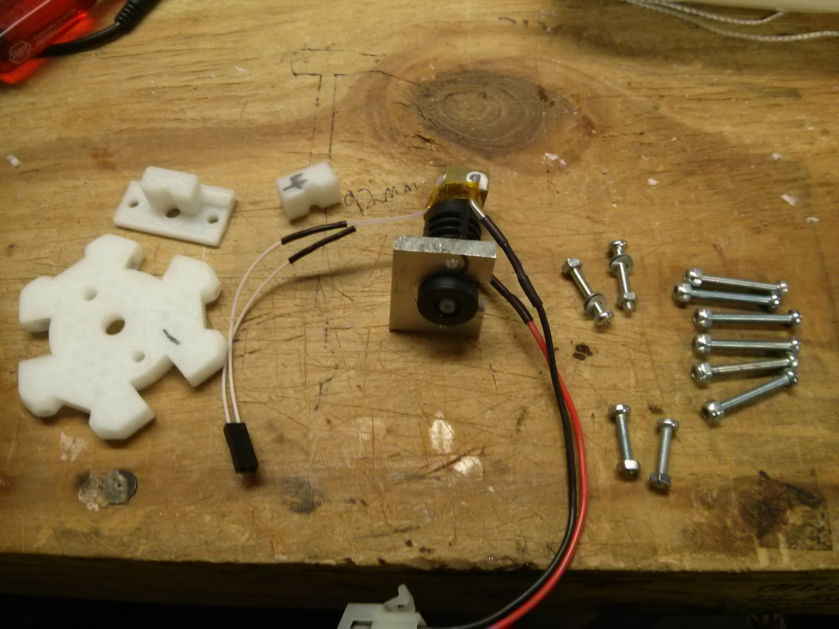
So if I'm going to bother to take it apart, I might as well put on a different hot end. The J head reviews well for PLA and Bowden extruders (that's where the extruder is not on the end effector), so I ordered one of those. It has a PTFE liner, which serves to define a specific point where this transition zone begins, and should allow the filament some chance of not jamming, even if it swells some.
Since I had nothing better to do, I took apart the hot end. I just cut the wires a little ways up the cable to get it free, and twisted it off (it was loose already). The filament was still stuck in the upper part that was still on the robot, so I removed that too, and then was able to shove the filament through from the other end and get it free.
I went ahead and attached crimp connectors (.1" and molex) that I now
have, so I can reattach it in the future.
If I am interpretting this correctly, I think the upper part (with the
PEEK) has within it a PTFE tube that is tapered at the end, and the
machined lower part has a matching taper inset into it that pinches the
PTFE tube when it is tightened down. So in the upper part, the filament
runs through PTFE, and in the lower part it is just metal.
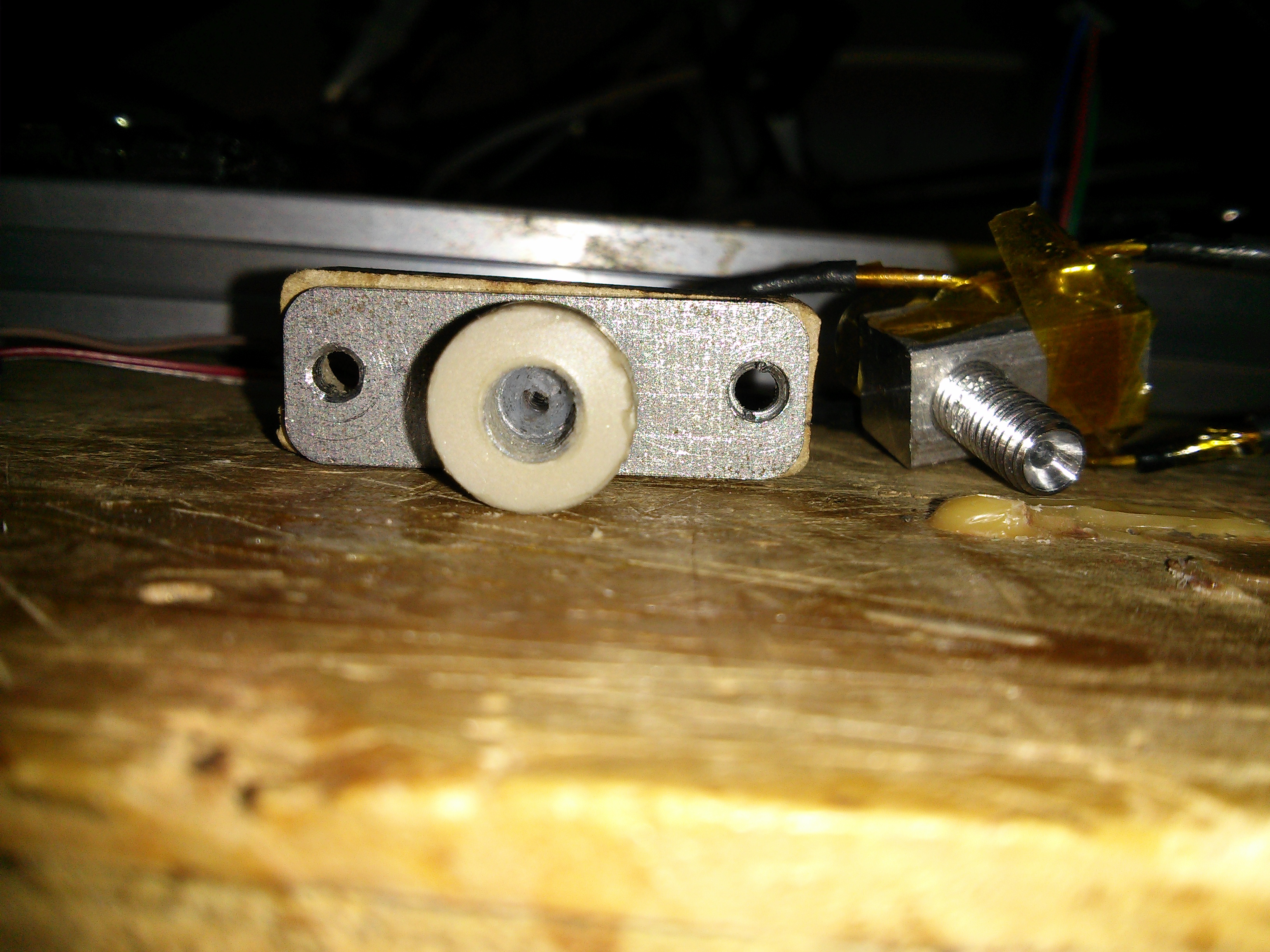
So while the filament retracted, it left a residue (a hollow tube, roughly) along the inside surface of the lower part. It was high enough up that it was not in the melt zone, but low enough that it was not in the PTFE. This prevented the filament from advancing forwards, because it could not fit within this hollow tube.
At the same time, there was a gap between the metal tube and the PTFE (because I did not think to tighten it down), and when the filament got in this relatively cold region it formed a solid plug at the end that was wider diameter than the end of the PTFE, so it could not retract through the upper part either.
I cleared the jam in the cold part by simply shoving it through as one piece. And I cleared the jam in the hot part by heating a drill bit in flame, and shoving it in there and when I yanked it, a lot of PLA came with it.
Now I can insert the filament into the upper part, and then there is a little restriction where it passes through the end of the PTFE, then it can move fairly easily and I can insert it into the lower part. However, when I assemble it together and tighten it down so there isn't a gap between the PTFE and the lower part, that causes it to pinch where the taper is. Then I cannot push hard enough with my fingers to get the filament past that pinch!
So I think the J-head addresses both of these problems. The PEEK goes all the way down to the top of the heater block, effectively insulating the lower part so that the entire aluminum part can come up to temperature even with a fan on it (preventing the forward jam). The second important innovation is that the PTFE is not tapered, so it won't pinch the filament when you tighten it down enough to not have a gap (preventing the retraction jam).
And I think the fan on the PEEK is supposed to keep the teflon part of it cool enough that it doesn't swell the filament. In the Mixshop hot end, the part you really want to cool is hidden behind a little piece of wood and the plastic of the end effector, so you mostly cool a part you don't want to cool instead of a part you do. Anyways, I'm optimistic.
Another potential source of difficulty is the extruder. The direct drive model Mixshop sent seems elegant to me, but it is not nearly as torquey as the geared (Greg's/Wade's extruder) model would be. Reports vary, but apparently PLA requires more pushing force. Anyways, I got a 0.5mm nozzle for the J-head so it should be relatively easy to push through.
Mixshop sent me an 0.3mm nozzle, I think. I would have said I prefer the 0.3mm nozzle for more precise prints, but realistically it is more important that I do not stress the extruder with excessive back pressure.
Finally got a spare moment to try to install the J head hot end.
I ordered the aluminum plate to attach it, and it is laughably too
large for the Kossel Mini.
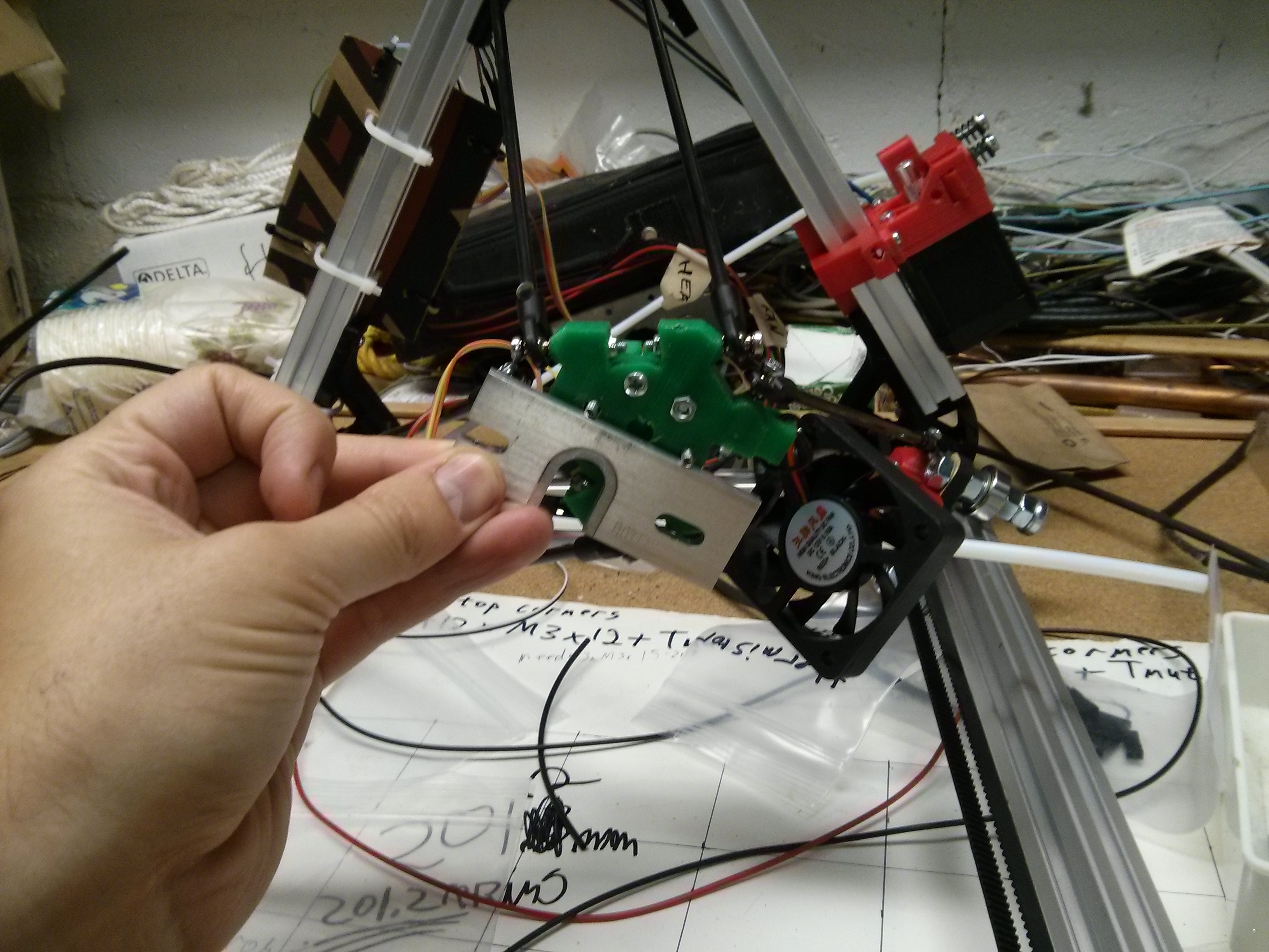
I have some 0.2in plywood sitting around, so I made a holder out of it
instead. I'm not really a wood worker. *sigh*
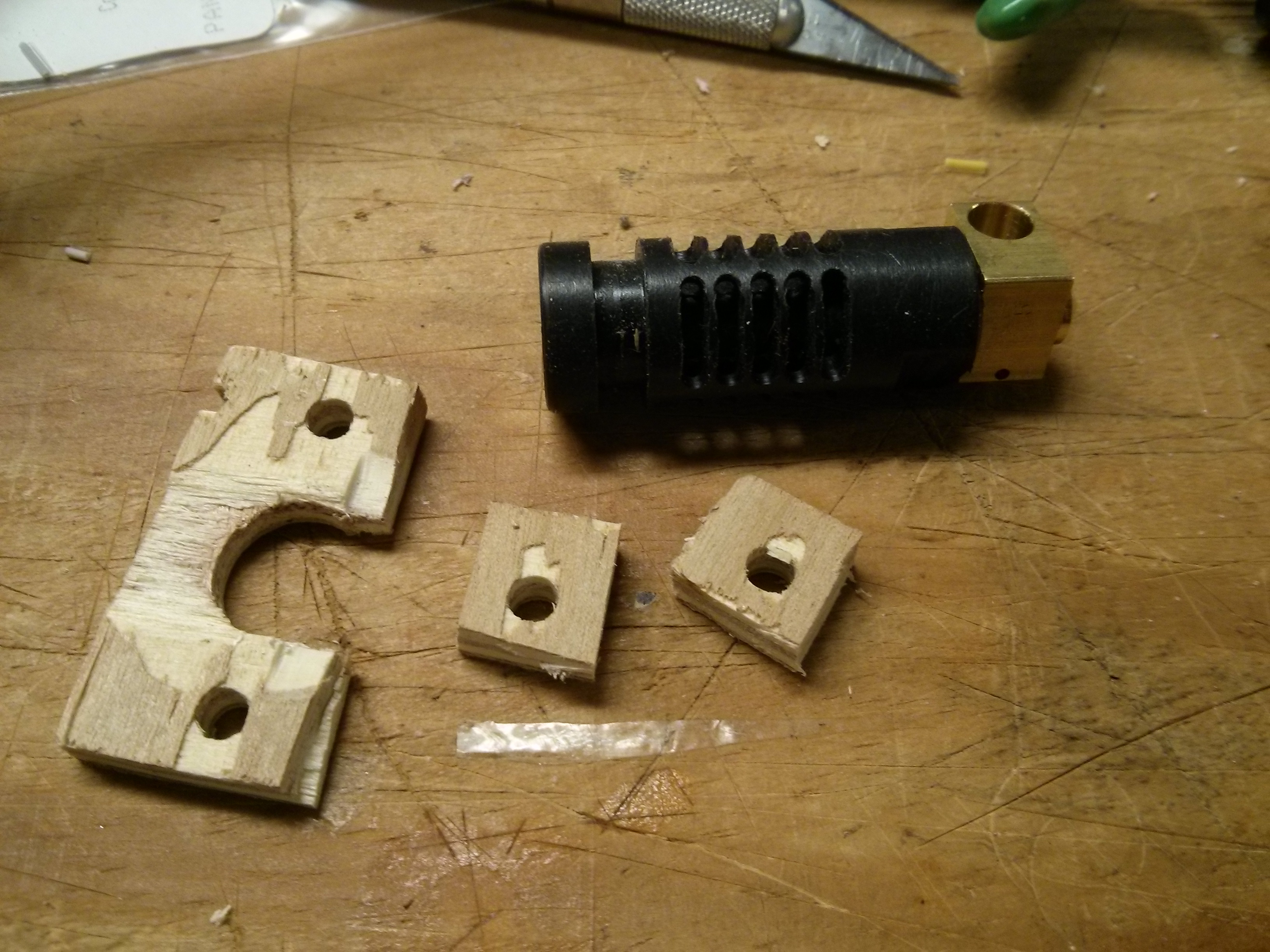
I also made a couple "washers" out of it for spacers. It all fit
nicely on the screws that were already there for the old hot end. It is
not 100% snug -- it can wobble a little bit. After I get it working, I
will want to engineer something more clever.
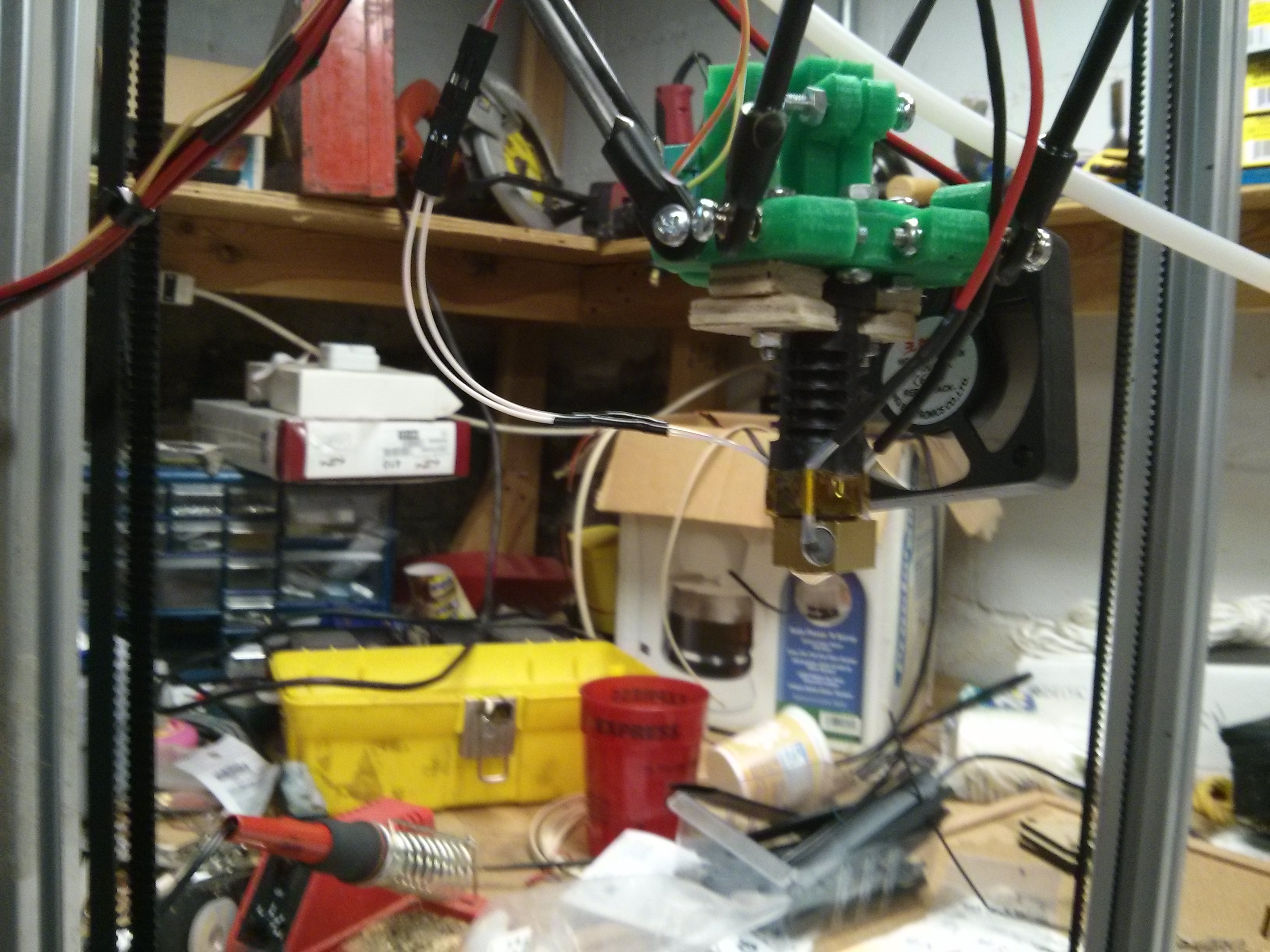
If you feed filament into it, it doesn't tend to enter the J head, because there is no beveled edge that is wider than the inner PTFE tube, which is itself smaller than the long PTFE tube that came with the Kossel. So you have to manually feed it past the catch, which I imagine will get on my nerves a bit. So I will have to engineer something better there eventually, as well, perhaps reusing the beveled edge from the original Mixshop hot end.
Remember to change the thermistor type (#define TEMP_SENSOR_0) to match your new hot end! From 1 to 5 in my case. Though they both seem about the same.
Anyways, I ran the PID autotune (M303 E0 S200 C8) again with the new hot end. The thermistor has a much faster response to a change in heater status, about 1 second compared to about 10. I think that's largely due to my poor assembly on the first one.
I set it to M109 S175 and fed filament into it with my fingers. It went pretty easily, I was able to do approximately 1cm/s of output without overcoming the idle drag of the stepper motors. I reduced it to M109 S170, and it was just a little bit tougher to push it in. I reduced it to M109 S165 and it took a lot more effort, so much that I was pushing around the end effector. So I think I will probably use around 175C in practice.
I pushed about 50cm of filament into it while playing with it, and while the extruded output was not perfectly regular, it was not awful, no visible bubbles or anything. This is really reassuring to me because this filament has been sitting open in my humid basement for two weeks. So the big spools that are sitting in a rubbermaid with a bunch of damprid (calcium chloride) should be just fine.
While retracting it with my fingers, I was able to pull a 2 meter thin (my micrometer says 0.001in) monofilament that was surprisingly strong.
To my surprise, even though the new hot end is nearly 1cm longer than the old, the Z-probe still reaches. However, it is now unusable because it rubs on the side of the hot end. I will do it manually.
The way automatic calibration works is it probes a 7x7 grid of points across the print area, and then it uses linear interpolation between the nearest grid points to provide the correction factor. So I added my own custom M403 command to provide the bed_level[][] grid points. And I wrote a perl script (probe.pl) to interactively generate G-code to manually probe the bed. What you do is enter some number of mm, and the head descends that much, until it is within a paper's thickness of the bed. Then instead of entering a number, you hit "n" and it goes to the next point. At the end it emits a file with 49 lines of M403 commands to initialize bed_level[][]. A little primitive but it will get me over the hurdle at the moment.
I had to increase MANUAL_Z_HOME_POS by 3mm so that the head will be able to touch in the "high corner."
It wasn't as much of a hassle as you would imagine, and it worked well. I can now move the head around at Z0.1 without it ever dragging or getting far above the bed. Except! If I go to the full corners of the printable area, which extend beyond the "probable area" (prounonced probe-able) by an arbitrary 10mm, then there is no correction beyond the probed point. So beyond the probable area, the head can both drag and go too high. That's no good because the extreme corners are exactly where the fact that the bed appears as a dome is most important.
Easy fix, just change DELTA_PROBABLE_RADIUS to be exactly DELTA_PRINTABLE_RADIUS. But now I have to do it over again. *sigh*
Since I haven't had time to work on it, I've been thinking about it instead. And I've decided Marlin's auto-calibration mode is best ditched, rather than improved.
The simplicity of the technique is brilliant -- it simply provides an interpolated Z offset based on the X/Y positions. It doesn't quite interpolate all the way out to the edge, but that's a correctable implementation bug simply by changing DELTA_PROBABLE_RADIUS to be exactly DELTA_PRINTABLE_RADIUS.
The trouble is that it generates horizonal error. I am not sure, but I think it would be roughly err=radius-sqrt(radius^2-adjustment^2). So in my case with a maximum adjustment of 1.5mm, I get 0.02mm when 60mm from the center. So, like, almost nothing. I just don't like it. I don't want my vertical alignment to introduce horizontal distortion.
So instead, or at least to get it closer, I'm going to try to calibrate it manually.
I have two main distortions. First is that the whole plane is at a slight tilt. I think that's because the endstops are not all precisely the same distance from the platform. I will fix that first, by moving the endstops, and then hot-gluing them in place so they won't tend to scoot around. Second, there is a slight spherical distortion -- the bed is further away at the edges -- which means the ratio between DELTA_DIAGONAL_ROD / DELTA_SMOOTH_ROD_OFFSET / DELTA_EFFECTOR_OFFSET is somehow messed up, I will just adjust DELTA_DIAGONAL_ROD.
Just leveling the endstops, I already have it down to +/- 0.3mm, which at 60mm is less than 0.001mm of error. So I guess I will just semi-auto-calibrate from here....and now it's calibrated, yay!
Oh and BTW the filament that is extruded has 0.024in diameter.
I actually tried to print something today, and it failed spectacularly because whenever an extrusion movement is specified, it messes up the other coordinates. For example, "G0 X2 E10" would wind up moving to X42, and also not extruding! I tracked this down to -- are you sitting down for this? -- it is interpretted as X = 2E10 = 20000000000.
I assume on top of some not so cleverness in the Marlin source, we've got a change in the underlying Arduino libraries that is damaging us too. But gee that one bug says a lot.
ACK! Such fail! Marlin uses strtod() instead of strtol() in all sorts of places where that doesn't make sense, so things you would not expect to be influenced by this bug are.
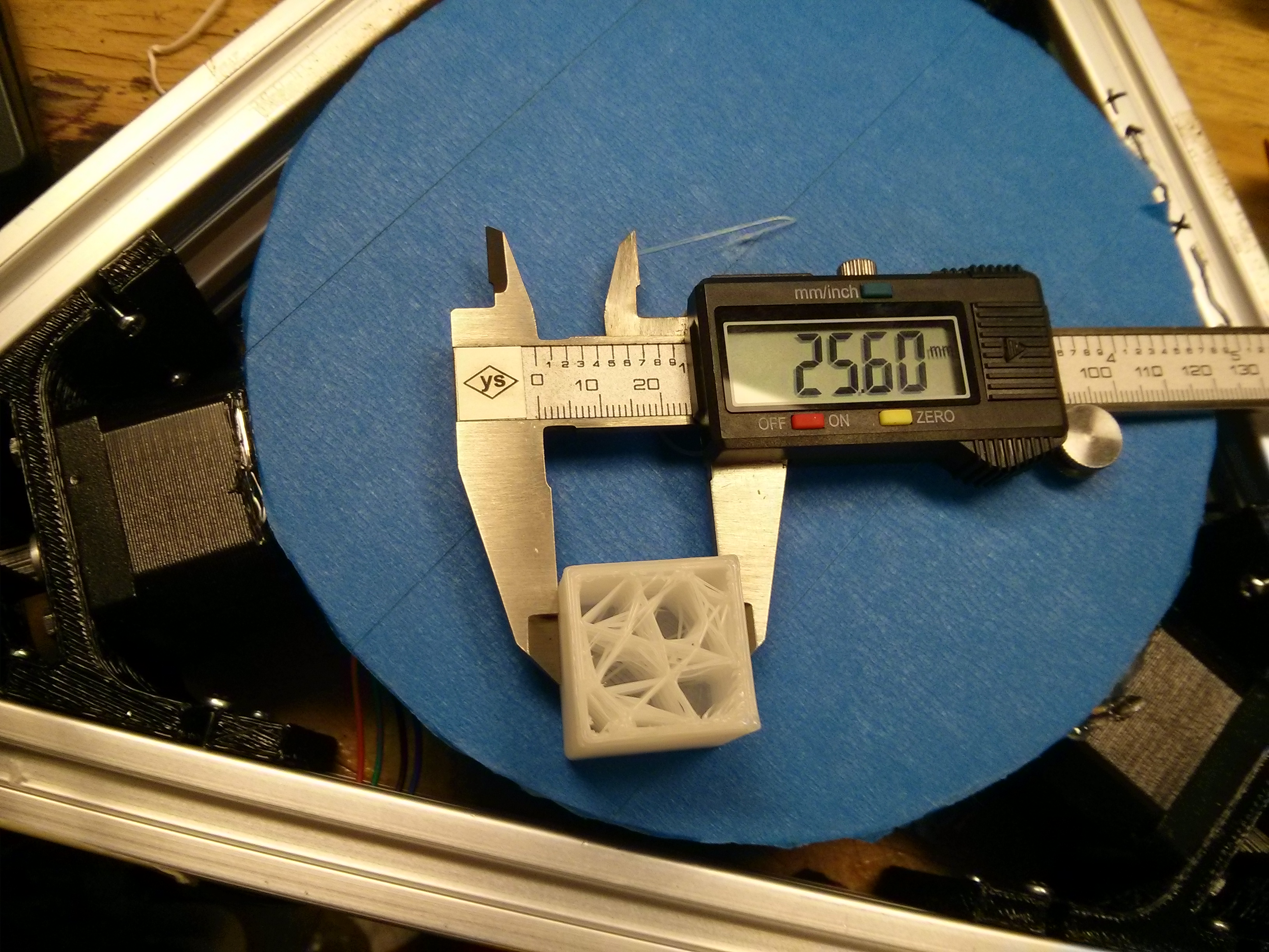
Anyways, I got it to work! My 5mm cube looked like crap, which will surely be a complicated thing to tune. But my 25mm cube is looking better. I noticed that when it got to the third layer or so, it started pushing around the acrylic platter a little. So I hot melt glued the platter to the stepper motors, and I increased my layer thickness to 0.5mm (that's my nozzle diameter).
And that seems to be an acceptable 25mm cube! I ran out of filament (because I had snipped off only a small quantity for testing), so the top is missing. And the corners need some work...
I think the trouble at the corners is related to retraction, so I followed the Slic3r tips for Bowden extruders, which reduced the retraction events substantially.
I also fixed a bug in my send.pl that made it wait either 100ms or 500ms between commands -- now it waits only 10ms if it can. That was making some specific steps pause in a bad way.
Now my 25mm cube looks a lot better. It still has some ripple in the edges because of the difference in velocities between inner walls and outer walls...when it slows down to do a finer job on the outer wall, it has a little tension in the filament and so the first bit of it bulges out from too much filament flow.
To improve this, I set Slic3r's Print Settings -> Speed -> External Perimeters to 100% (used to be 70%), so that it won't be any slower than the inner perimeters...I went ahead and left Perimeters at 30mm/s though, in hopes that will be fine.
Also, it moves faster in the infill area, and extrudes faster, and in that area the extruder skips (the stepper motor is not strong enough to push the filament)! In fact, it skips on the top too. So there are gaps in the infill, and the top. And the worst of it is that the PTFE tube eventually pops out and then it stops extruding at all -- which happened halfway through the top layer, ruining an otherwise pretty decent 25mm cube.
I think in the short term I can fix both of those problems by increasing Filament Settings -> Filement -> Extruder: Other Layers to 180C (was 175C), so it will be easier to push filament through the hot end. I also decreased Print Settings -> Speed -> Top solid infill to 30 mm/s (used to be 50mm/s), so that the top layer won't tax the extruder.
But in the long term I will want to re-engineer the PTFE holders and switch to a geared (Wade's) extruder. I think it prints well enough for the moment to achieve both of these goals!
Also while doing infill it jerks around powerfully enough that the fact that my plywood J-head hot end holder isn't quite rigid becomes relevant. I don't really care, because infill is pretty low priority and it is stable enough at reasonable speeds, but eventually I will want to do something more rigid (such as figure out how I can use the aluminum plate to attach it).
In addition to those other changes, I made the infill speed only 40mm/s (from 60mm/s), and I changed the layer height to 0.2mm. That last one is a big deal! I wasn't sure if it would work or not, since I hadn't tried anything like that before.
This time I decided to do something totally different. I printed a 20mm cube!
It is incredible how well 0.2mm layer height works! It makes a very nice thin neat trace as it goes now, and the result is incredibly neat.
And it really sips plastic. My 20mm cube with 0.3 honeycomb infill is only 5.4g, so I could print almost 200 of them from one spool.
This time it held together to the top, but the top is still not perfect. Where it bridged over the infill gaps, it didn't extrude enough to make up for the fact that the bottom layer sagged. So I changed Slic3r from 3 top layers to 7 top layers.
Oh well, it still doesn't have a perfect top on it. The bottom is just fine, but it is like it needs to extrude more for the top. Maybe it is just sag, but more layers doesn't seem to fix it on its own. I bet it would be a little more reliable with a larger (like 0.5mm) layer height.
Another thing I noticed this time, about 75% of the way up my piece, there is an apparent horizontal shift along one axis -- all the layers past a certain point are about 0.2mm to the side. That is not preferrable. I hope it is something relatively innocent like the hot end holder I was going to replace anyways....
Oh and for what it's worth I haven't had any trouble popping these pieces off of the blue painter's tape. It sticks good, and then comes off with just a little finger leverage.
I have had more than a month of good functioning from my Kossel. I have printed about 60 meters of filament, a variety of useful things for around the house, and also new parts for the printer.
I abandoned my send.pl for a new send.c. It has a much better design, but the main feature is that now you can pause/resume while printing from a file, with reasonably good results. I made a pile of little hollow cubes, and paused it before it printed the roof and dropped a bead in, and now they are rattles. I tuned it until I could barely discern the flaw in the print where I paused it. Pretty spiffy!
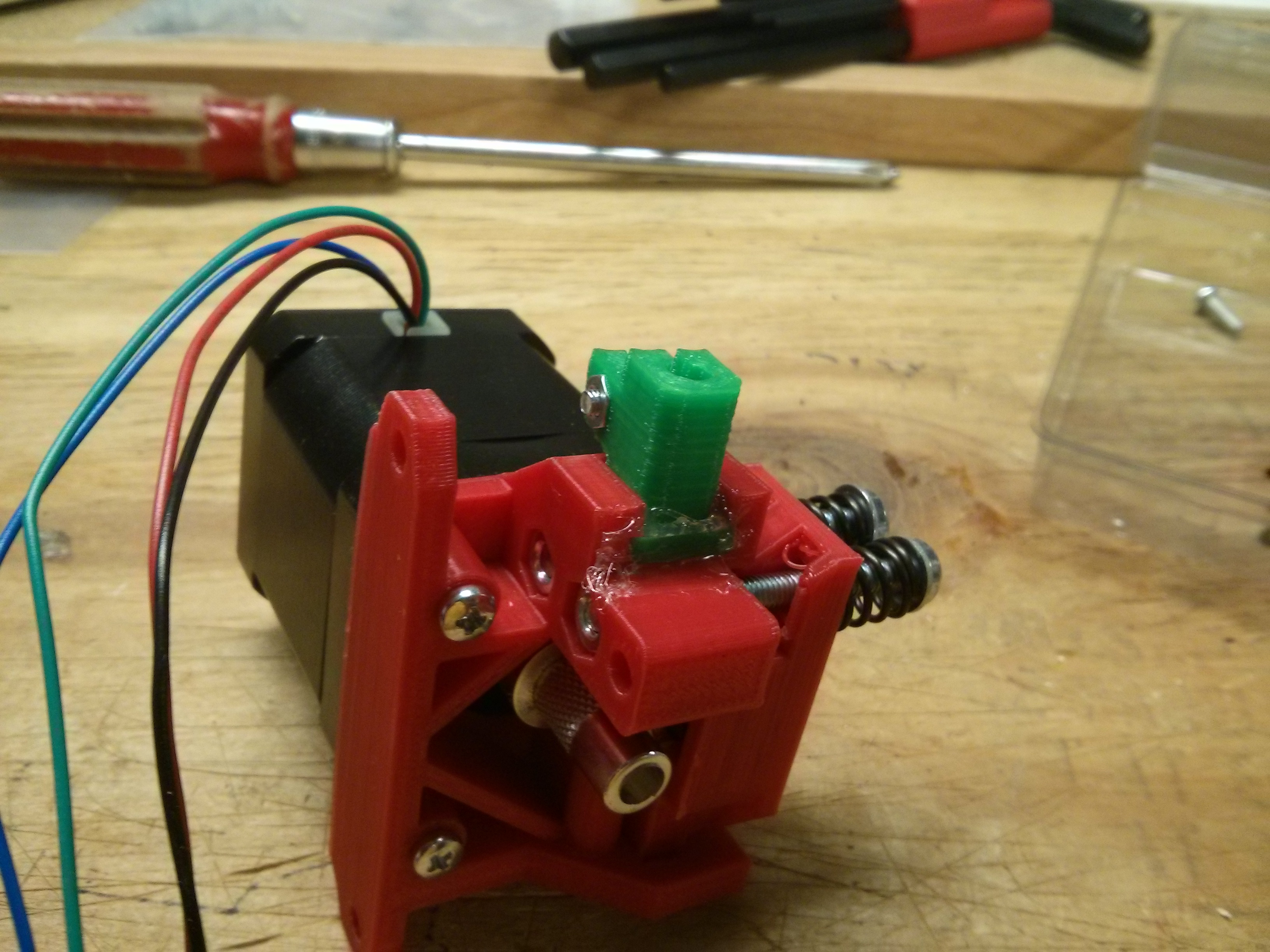
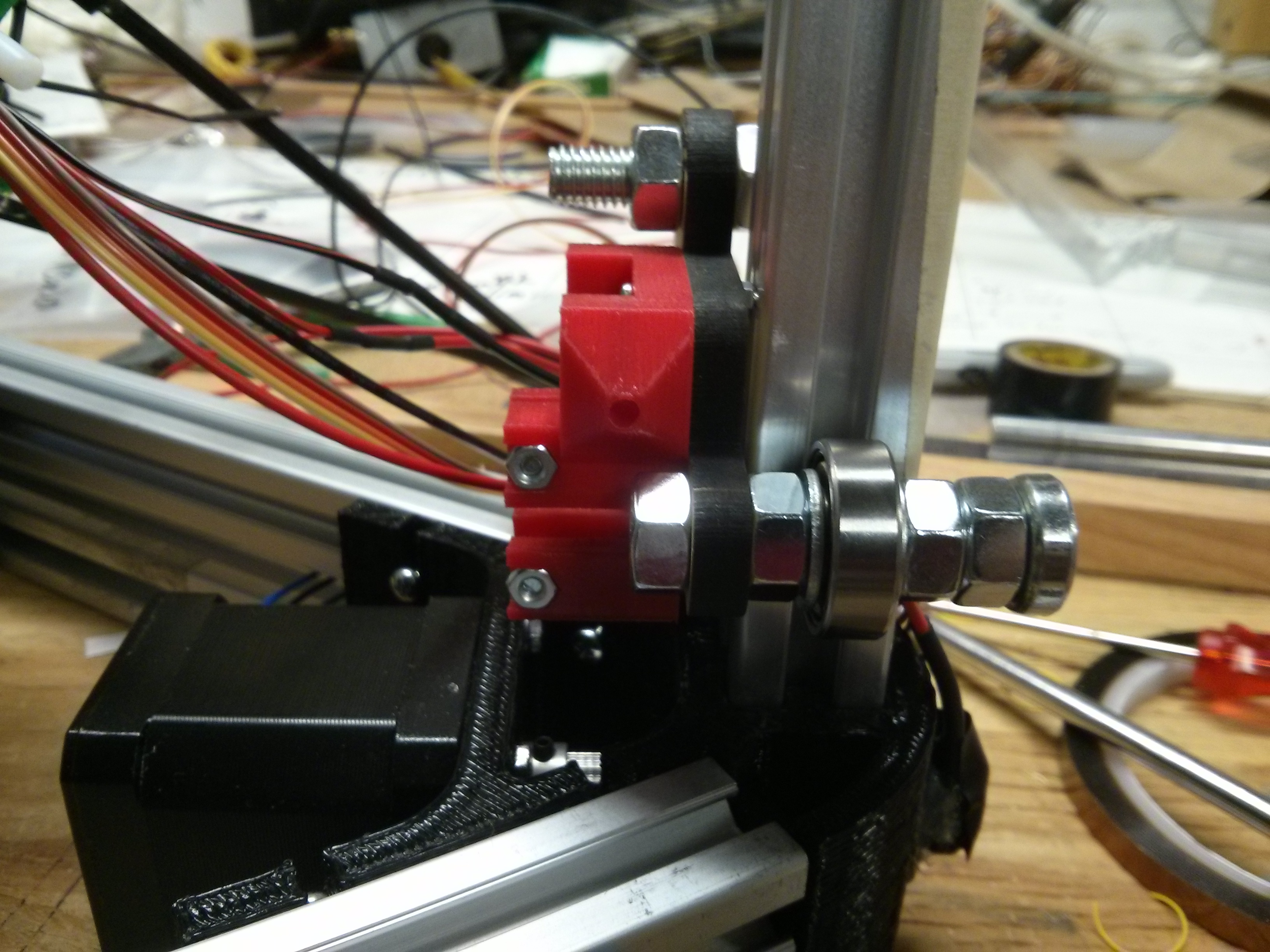
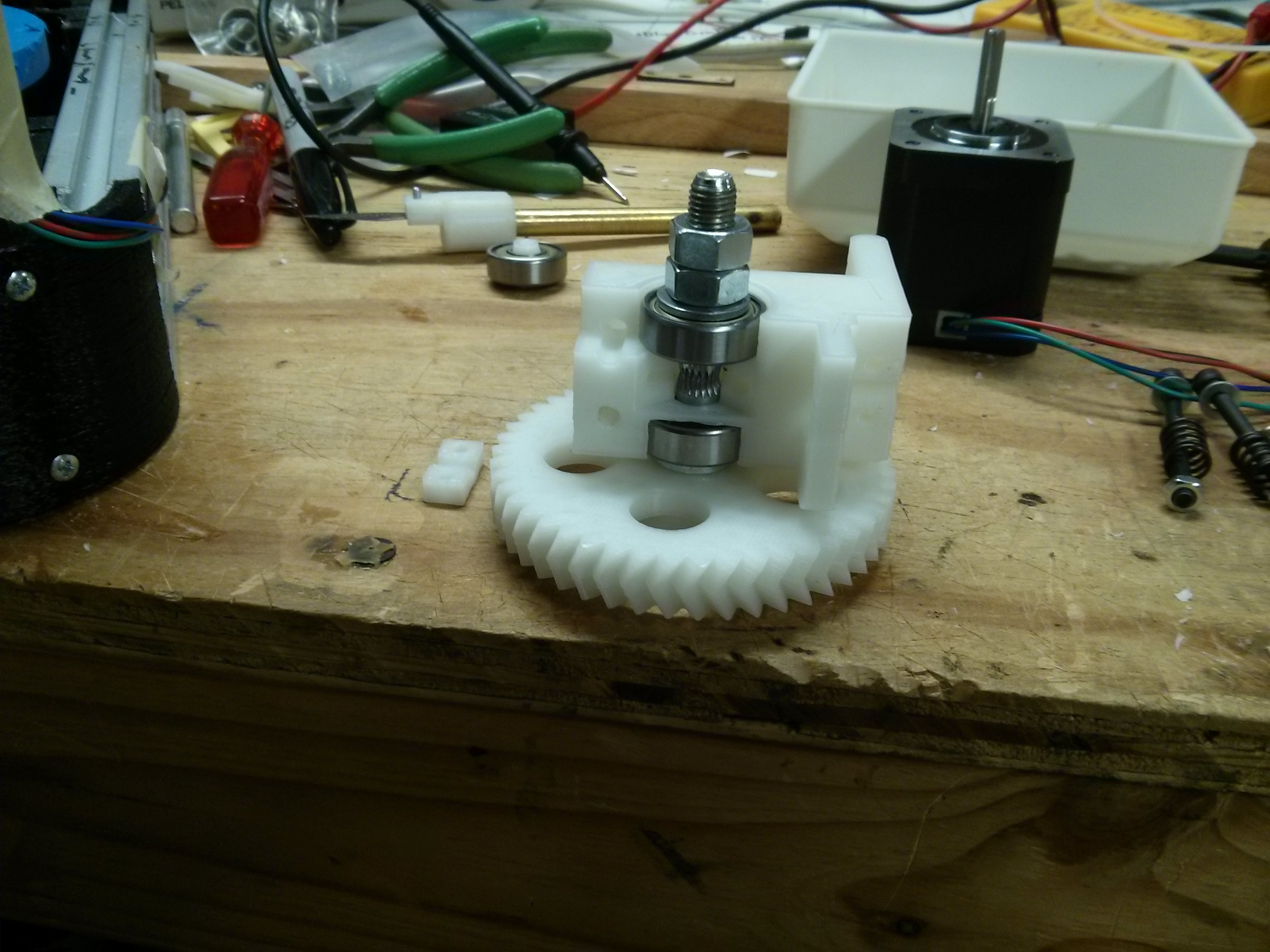
Anyways, I started on custom parts by making an improved PTFE clamp for the extruder, and that worked so well that then I wanted to make one for the end effector too, which suggested a new end effector. Then I wanted to switch to 4mm OD/2mm ID PTFE tubing, so that it might have less Bowden hysteresis. The filament actually has a little resistance in this tighter tube, so I figured to be safe I oughta switch to a geared extruder. So I've got all the parts for the new end effector and geared extruder ("Greg's Greg's Wade's"), and now I am going to install them all at once. Makes me nervous.
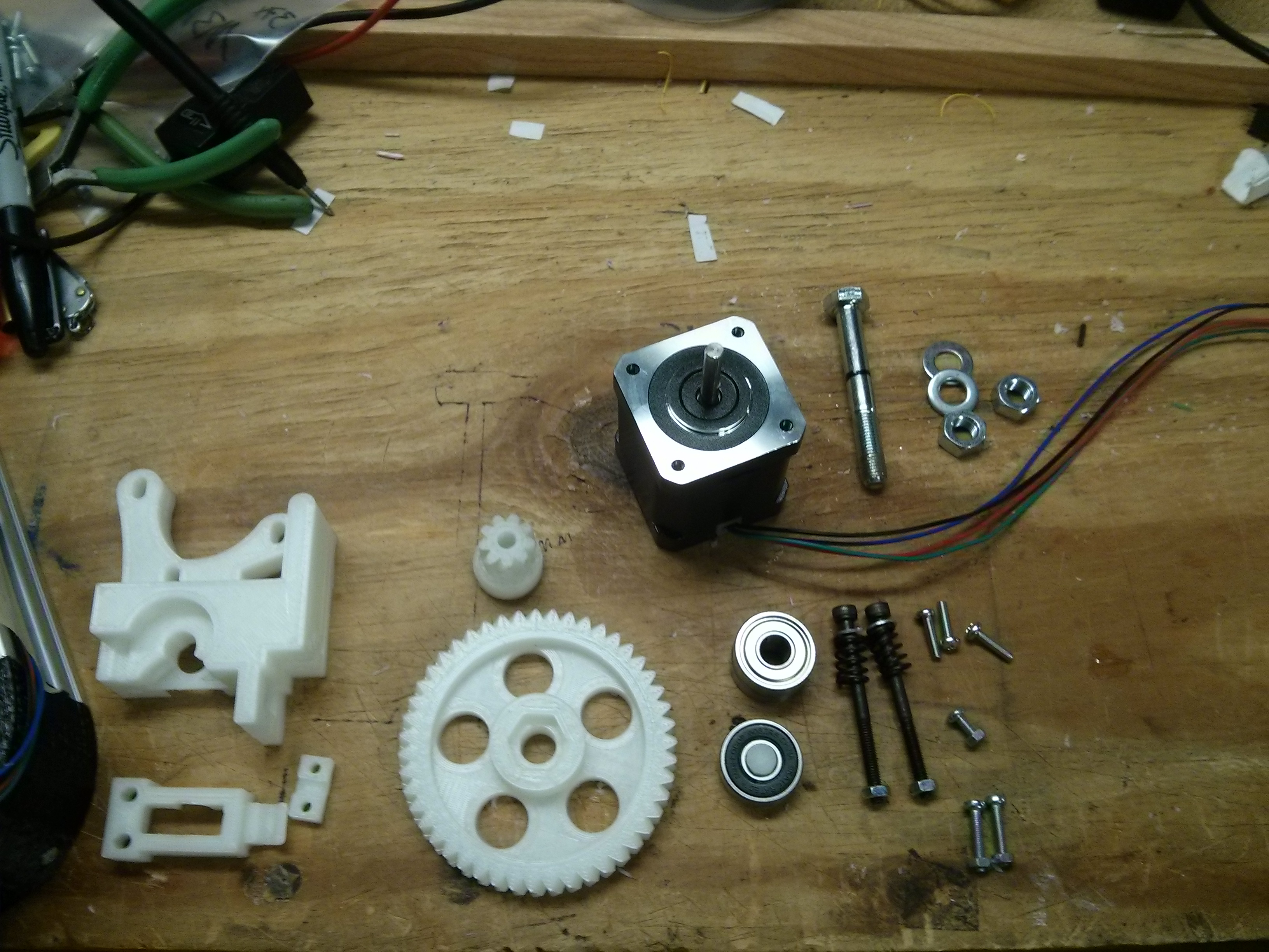
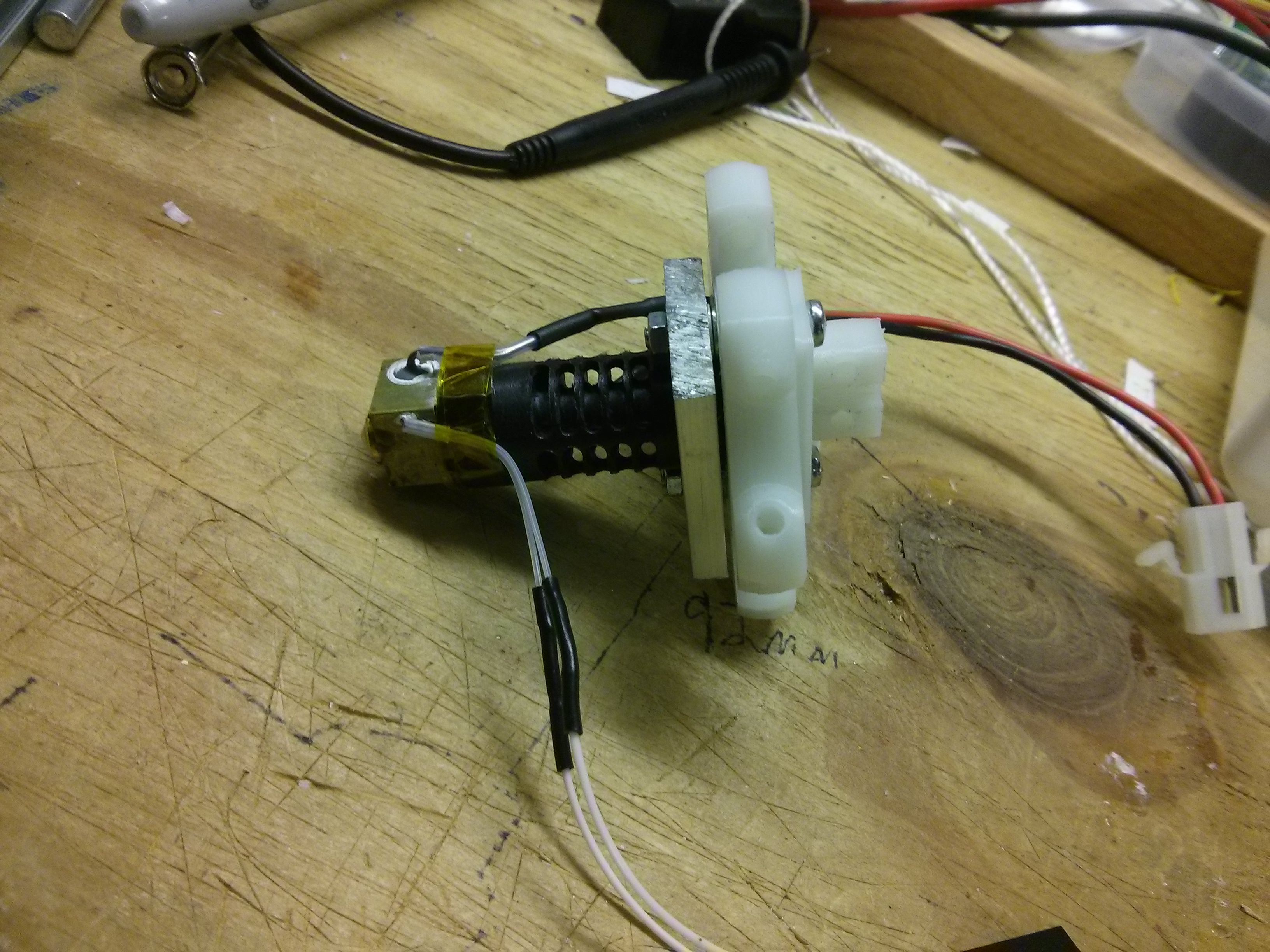
I test assembled the big gear assembly on the M8 bolt, so I could
sharpie in the line where the filament crosses. This is where I will
hob it.
I got a "1/4-20NC [#7]" tap at the hardware store. It was surprisingly affordable. I put a stack of washers on the M8 bolt and chucked it into the drill press, and put the 1/4" tap in my hand-held drill. The drill press remains powered off (in fact, I undid its drive belt) while I held the spinning tap against the bolt. I saw it on youtube. It worked better than I expected it to, but I had to throw away the first one because I made a flat spot. Slow and steady, at least at first, wins the day.
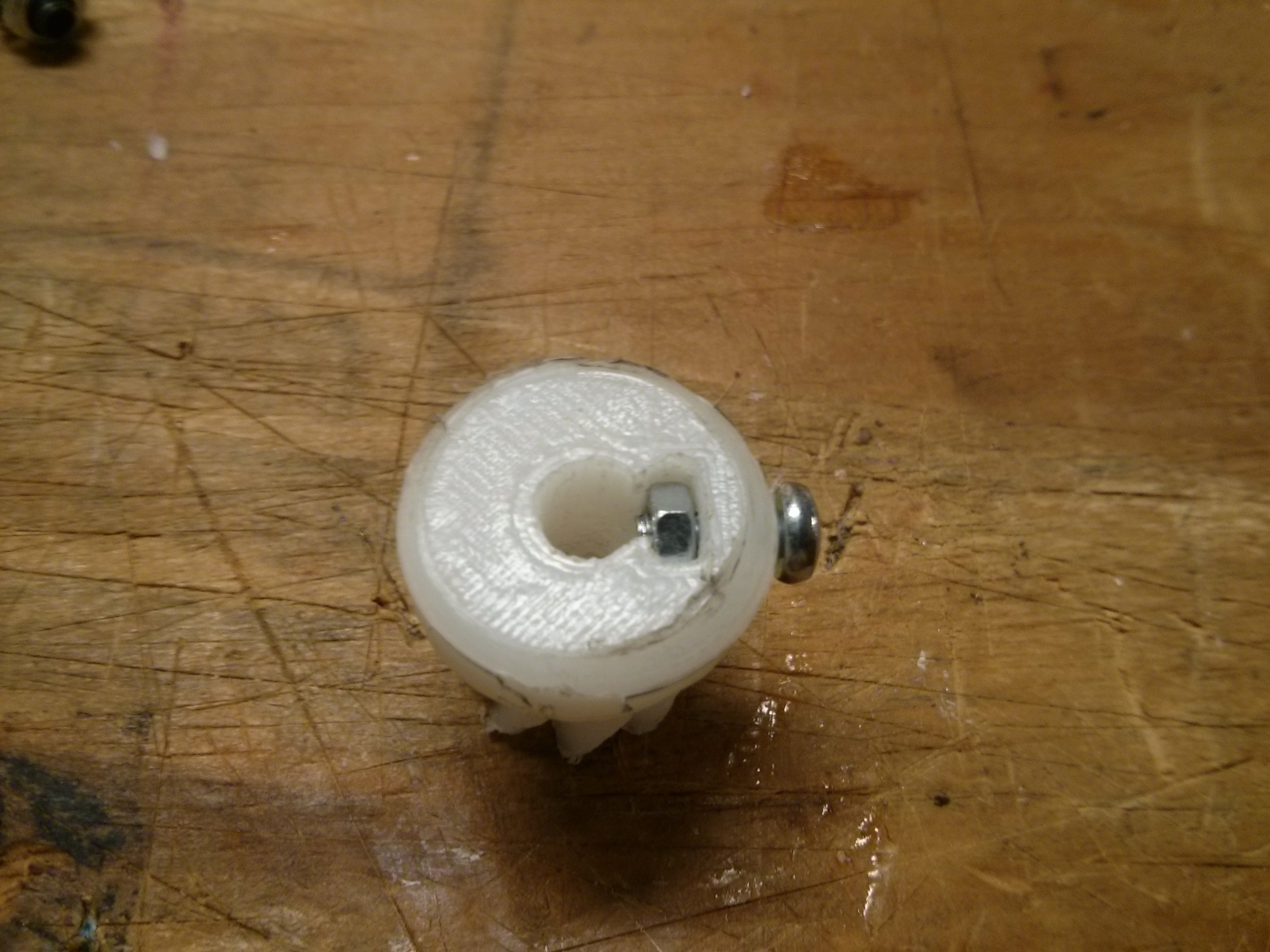
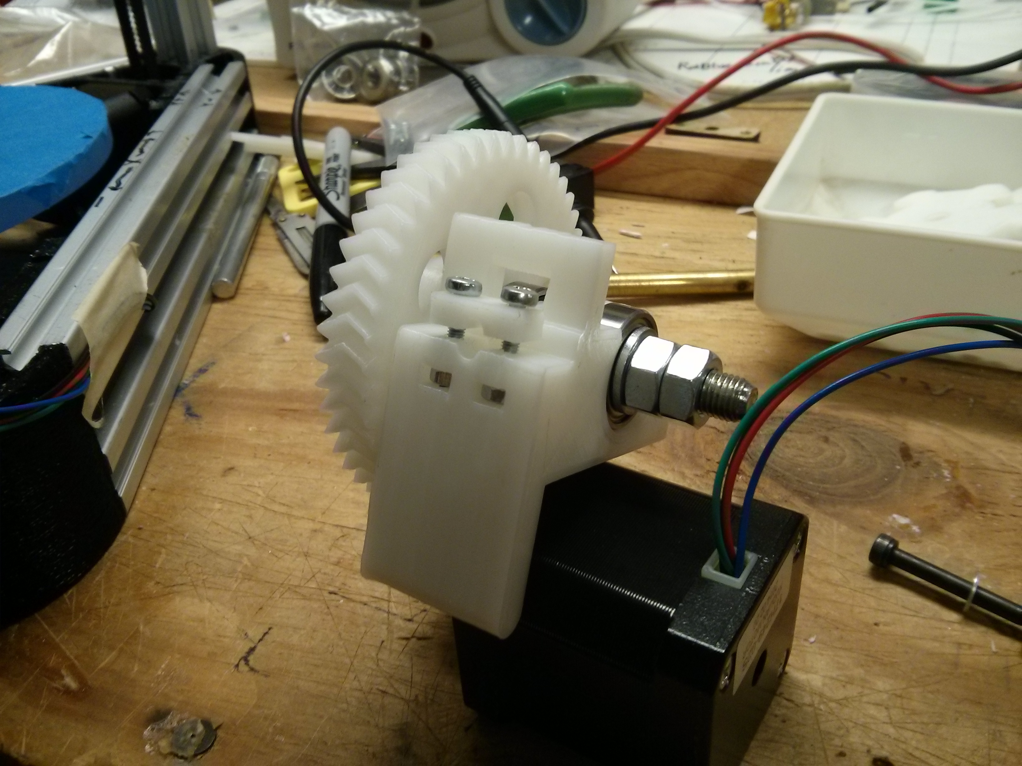
I used the M3x8 and nut to form a lock screw in the little
gear:
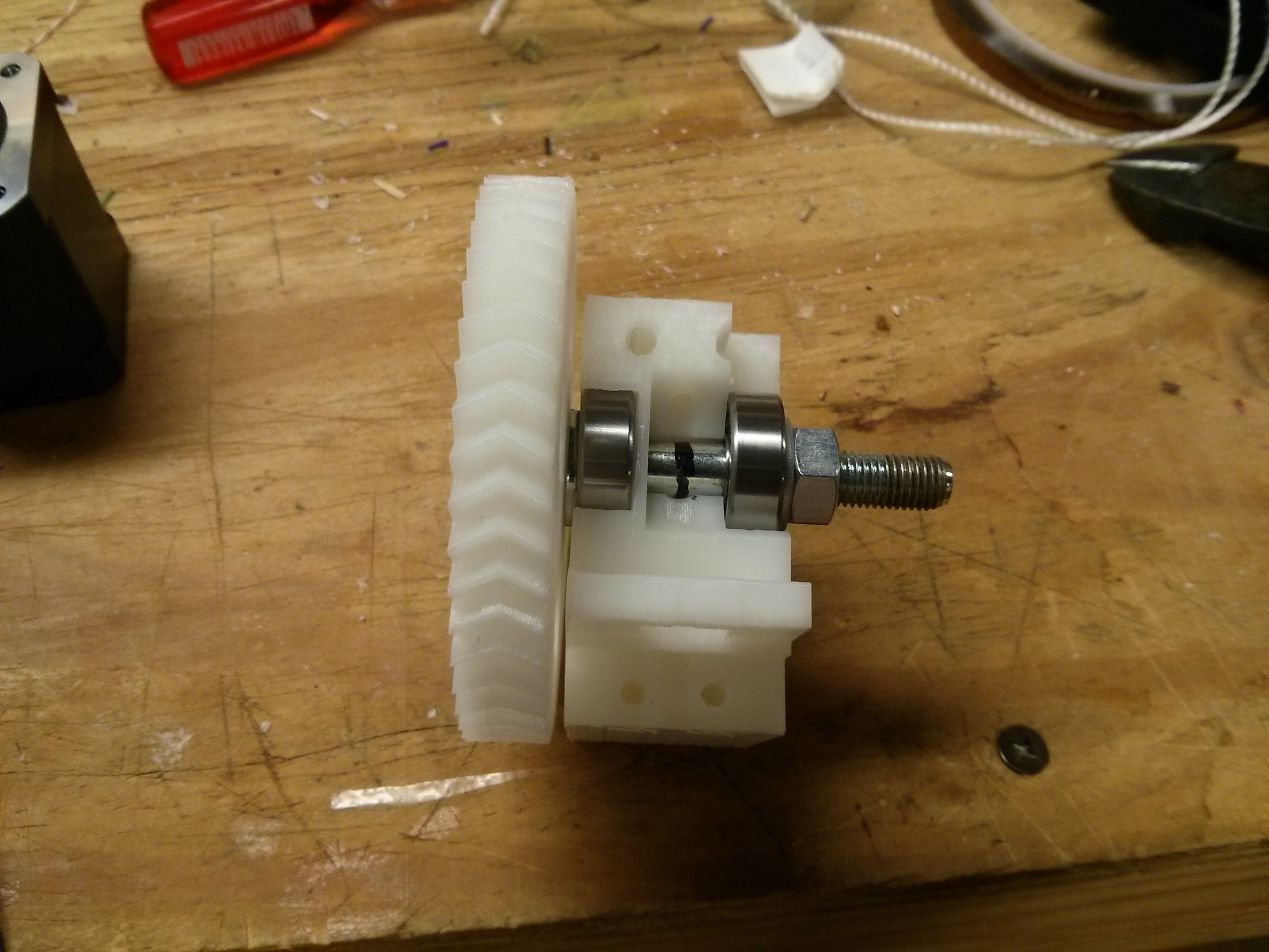
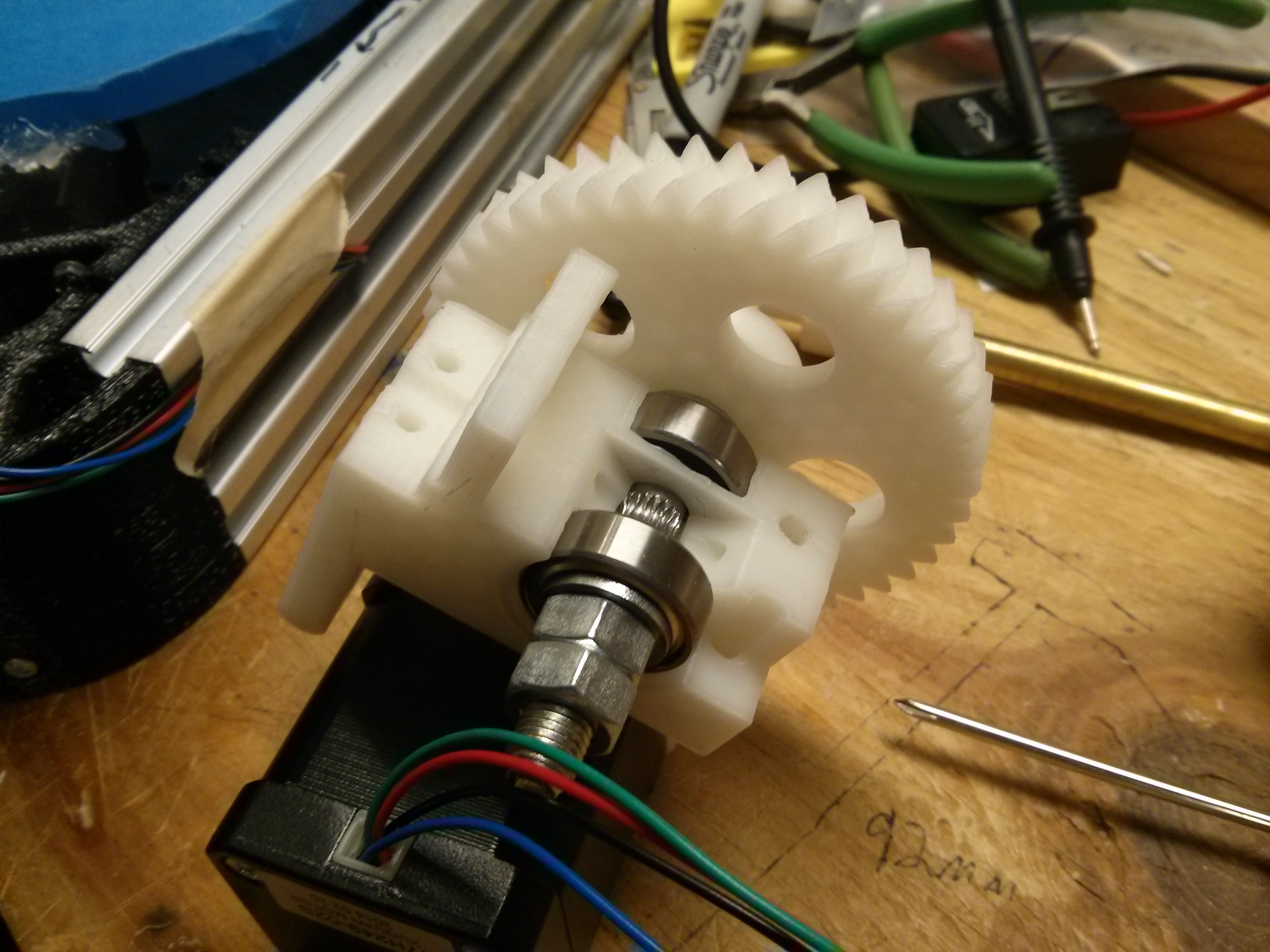
I assembled the big gear bearing, an M8 bolt with: large gear (use
hot melt glue to eliminate slop in the interface with the bolt head),
washer, 608, extruder body, 608, washer, 2 nuts tightened against
eachother (and/or nyloc):
I installed the stepper motor:
And then the M3x16s with nuts to attach the PTFE clamp:
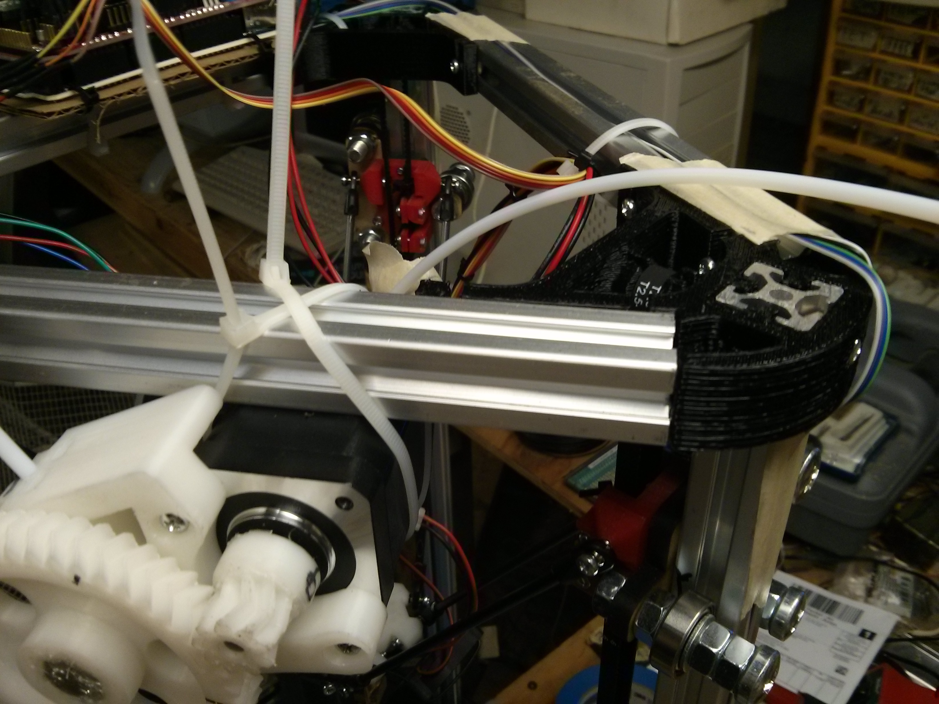
And then the M4x50s and springs to attach the idler block.
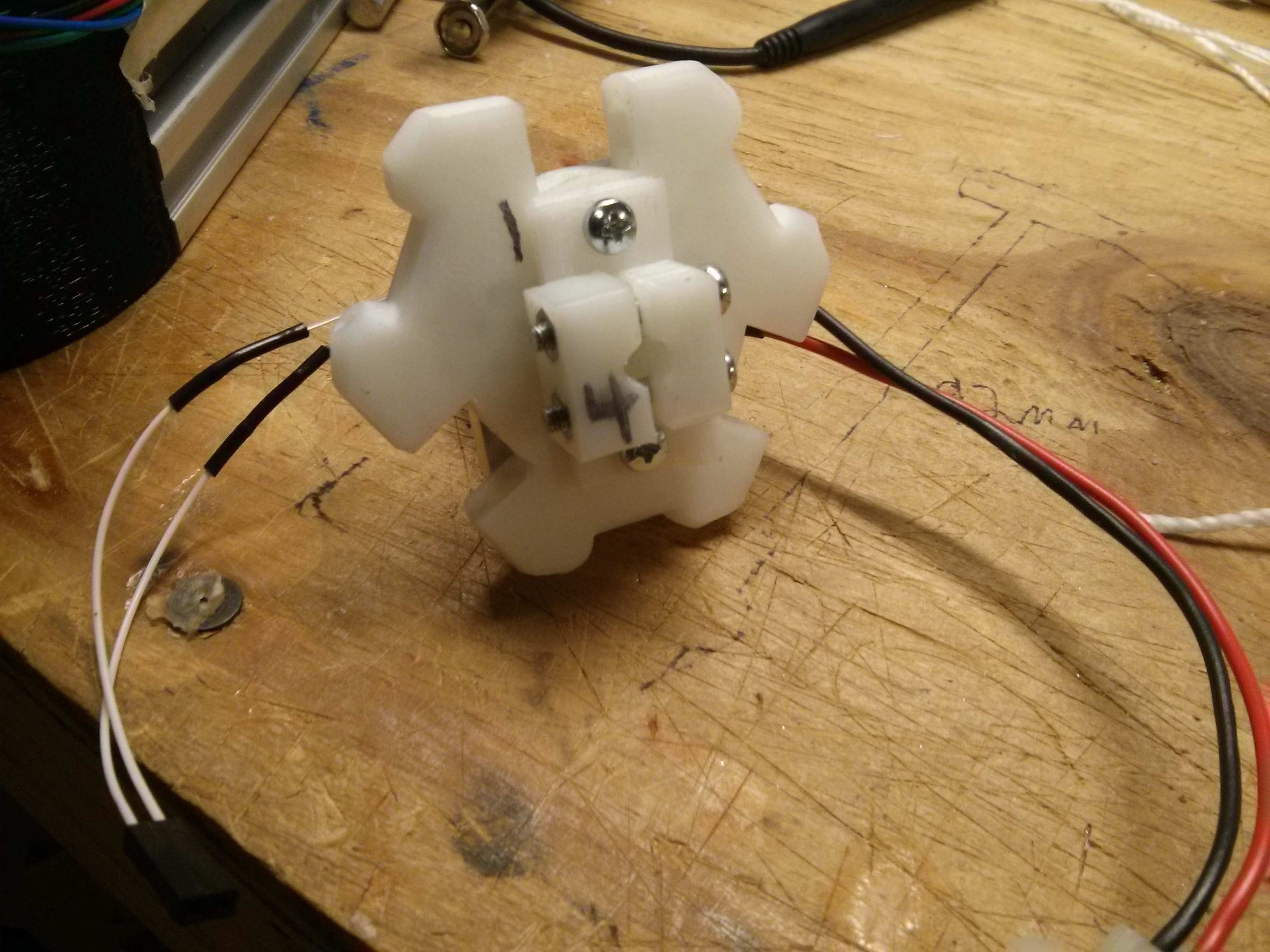
I attached it to the frame with a couple zip-ties around the motor.
Not exactly elegant, but functional:
I had to cut down the mounting plate that came with my J-head. To my surprise, the slot in the mounting plate for the J-head was 11.88mm while the J-head was 12.01mm, and they would not mate even with a good deal of pressure. A bit surprising, but easy enough to solve -- just a couple moments with a file. But mostly I cut it down to a much smaller size, and drilled new mounting holes through it.
That was a real triumph for 3D printing, btw, because the mounting holes were not 100% centered (so sue me), but I simply measured them as well as I could and put an offset into my SCAD file. Pretty neat, huh?
I stacked the main components that onto the M3x20s:
PTFE holder base, end effector body, 2 washers, J-head mounting
plate, nut:
I used the other M3x20s to finish the PTFE clamp:
Then I attached it to the arms, and used a bit of bent-up 1.5mm steel
fence wire to attach the fan. I inserted the wire into the hole by the
PTFE
clamp, with a dab of hot melt glue to give it a sense of place:
I cut an 850mm length of 4mm OD/2mm ID PTFE tubing, and put it all together. Be careful not to leave any swarf, because if it gets into the hot end, it will clog (the hot end cannot digest PTFE).
Re-calibrate X/Y/Z (new bed leveling matrix), and E feedrate steps, and it works!
It seems to need a higher extruder-multiplier (I guess I did not calibrate it quite the same as last time?). Also high-feedrate (like F5000) extrusions no longer work, because the motor would have to turn some insane RPM (the equivalent to F25000 before) to accomplish that. So I need to tune my slic3r config again...
Pfew, I was afraid I'd never print again. Maintaining a working printer is scary.
I think the last thing I really wanted to improve about this printer is that its carriages interfere with the carbon fiber rods too much. I have to limit myself to a 119mm diameter, which is easiest to enforce as an 84mm square. It is lame.
I decided to design new plastic carriages with reduced interference. I am putting a lot of faith in the strength of my red easyfil "impact modified PLA".
I assembled all the nuts, washers, and bearings onto the M8s. Kind of
a pain - maybe I should not have put M8 nut traps on the back-side of
it.
I used the 4-40s to tension it onto the rail. Note it would be easy
to adapt it to something like M3x35 or M3x40 instead, but the store by my
house carries SAE. No need to get these too tight, I hope. It is
probably possible to break the plastic by over-tightening these.
I attached the arms.
I attached the belts.
Then I did that two more times.
Then I redid the blue painter's tape on my bed, because the old one had gotten kind of gouged up and poorly-patched. And I have to re-calibrate anyways...
Then I re-calibrated my printer.
I am coming up with a diameter of 158mm now, which means a square that is 112mm on a side. The platform itself is 165mm, so mechanically I think this is just about as good as I need to do. It would be nice to be able to print the whole circle, though, instead of just the square...I mean, we're talking 4.4" vs. 6.2", that could be pretty crucial for something like model airplane wing ribs.
If I could make the mechanics even more non-interfering, I could conceivably support, say, a 158mm square....except that the arms are only about 170mm long, and you can tell already they are almost getting to straight -- it simply can't mechanically reach significantly further than it is.
And it prints again! Yay!
The printer is fairly flawless from my perspective now, but I had the idea I would replace the tape that I have used to trap the cables inside the slots on the outsides of the beams. The tape is slowly peeling. Also, it doesn't push the cable inside the slot at all, so it tends to be right at the surface and come out a little between pieces of tape.
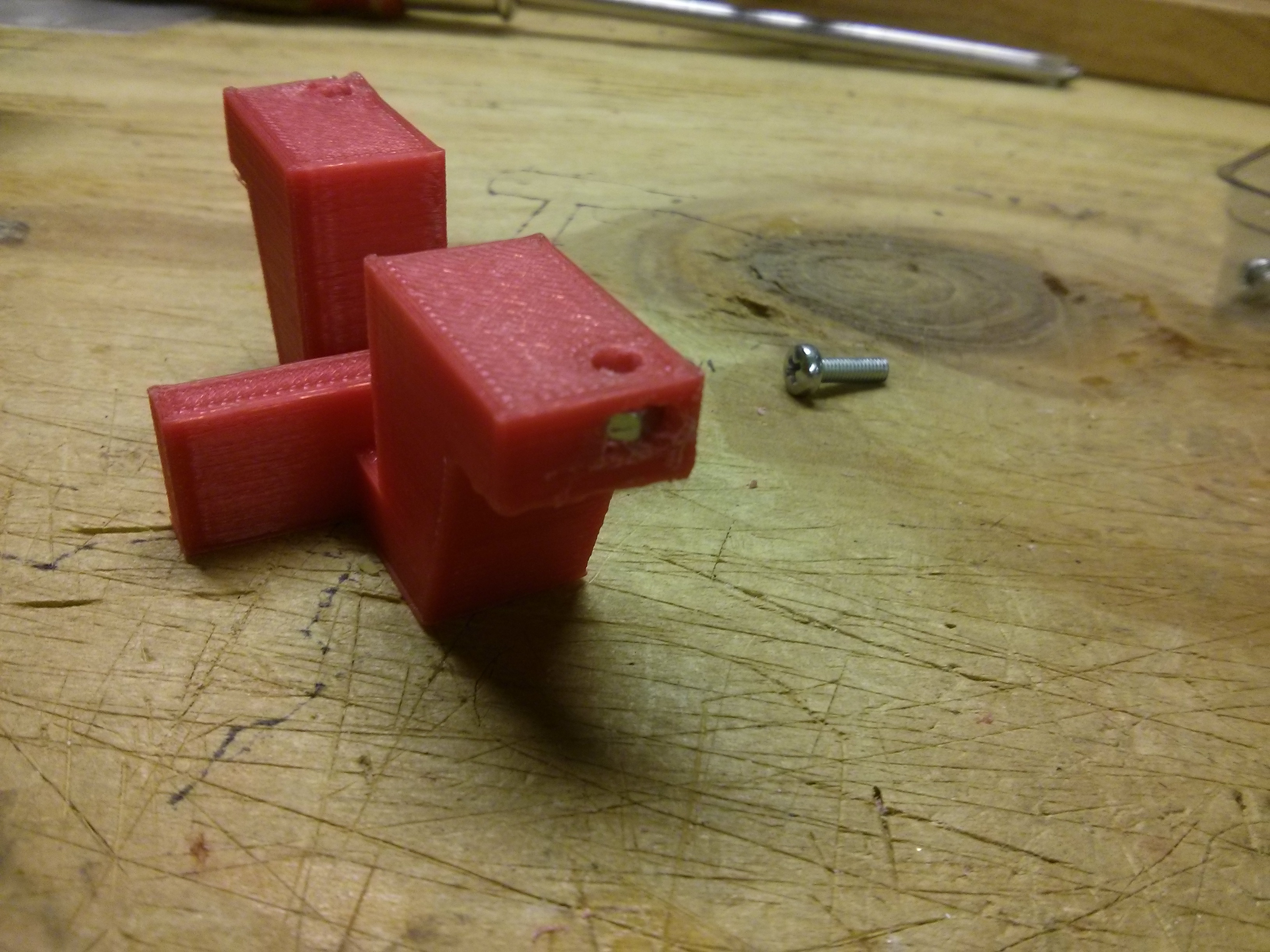
In order to make a plastic part for this purpose, it must not extend more than about 1mm beyond the surface of the beam, or it will catch on the carriages! So I made it only extend just enough to guarantee it will have strong friction to stay in place (gripping the inside and outside of the beam). Then I made a couple slots in my tiny plastic piece, so I can use needle-nose pliers to turn it into position.
The other problem is that since the pieces are so small, the layers do not cool at all before the next layer is put on top. This makes very non-uniform parts. I solved that by printing 9 of them at once, so each layer cools while the print head is visiting the 8 other parts.
Here are a few printed out:

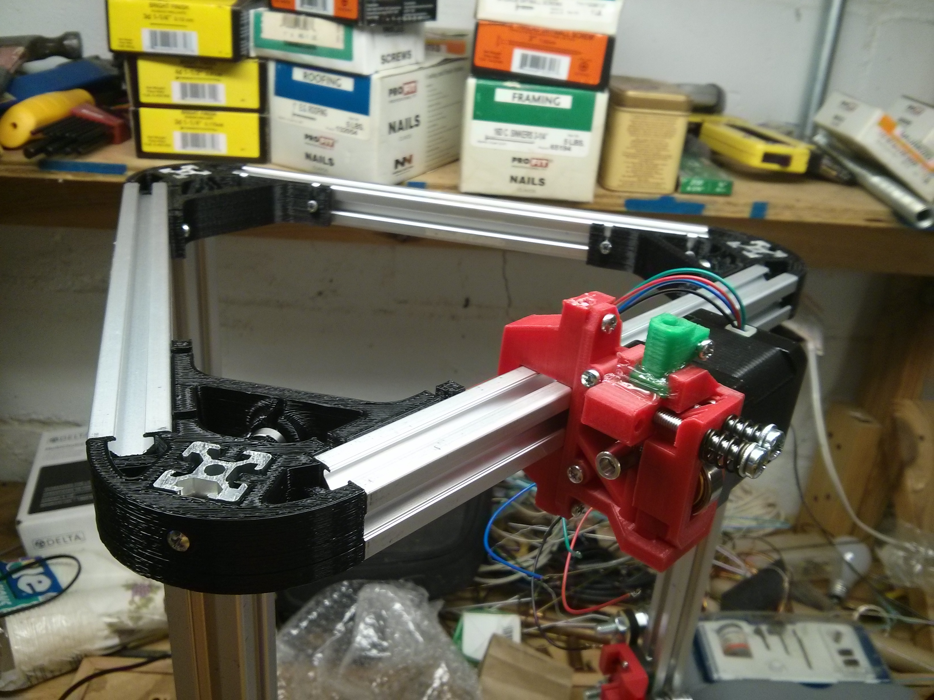
Here they are, installed:

Not really worth the effort, but a satisfying result and a fun engineering challenge. Making very small and detailed pieces is not as easy as making bigger pieces, but it is good to know it is possible to eventually come to a good product.
Also, while printing this I noticed that my extruder was behaving a
little eratically. I cleaned out the bits of PLA swarf that had
accumulated in it:

The photo doesn't really capture how much it really needed it -- I even found some clear PLA in it, which I haven't used in a long time!
My printer has been working well for me. I print things out every couple of months. I've got 42 projects in my 3D directory, and a lot of those I have printed multiple times as I've refined the design. They haven't all been successes, but I've really enjoyed the ability to engineer my own doodads. I highly recommend it.
As of late, I've been noticing one flaw in the kit. It hard locks whenever a fan turns on or off anywhere in the house. Unfortunately, the heater loop seems to be the only thing left running, so it's a bit worrisome. My assumption is that the power supply (apparently a surplus laptop brick) is crappy and dying. I took one of the PC-AT power supplies from my pile, and it is a lot worse! So I'm just living with it for a while... A bummer, but not bad for the price I suppose.
Anyways, I've now used up almost all of my red Form Futura EasyFil PLA 1.75mm that I bought back in Oct 2014, so I feel like I can review it.
It replaced some no-name natural (clear/white) PLA that was no good. With the clear PLA, a lot of the objects I printed failed if they were subject to any repetitive stress or impacts at all. I would say overall about half the things I printed wound up breaking, and of the products that have survived, I've generally had to replace one or more components. I also found that if I left unused clear PLA filament sitting on my printer for a couple weeks, it would become brittle there too. I got it because I thought the dyes made it weaker, but I was exactly wrong.
By comparison, the EasyFil is perfect. I use it at 205C, and it works fine in my printer. It never jams or does anything untoward. It sticks well to blue painters tape on my unheated bed, and I don't recall my parts ever warping up off the bed on the corners with it. I can leave a few loops of it sitting on my printer in my humid basement for months, and it still prints fine without any bubbling or brittleness.
I'm not super ambitious in my designs, but it has never let me down. I only remember breaking one product, an adaptor that fit on the end of a 5mm hex wrench and then drove a weird large cruciform plastic screw. I had to unscrew 24 things, and it cracked on the 20th one. Not bad, given how little leverage a 5mm hex wrench really has on plastic. It was a real time saver compared to the other hacks I came up with to remove them.
So I can't really compare it to anything else, but on an absolute scale, it is very good. Now that it's run out, I've got a spool of blue polymaker PolyMax PLA I'll be running through...
I finally started printing with the blue PolyMax PLA.
To calibrate it, I tried some different temperatures...at 180C it won't extrude. At 190C, it will. So I tried it at 195C, and the print came out alright but it had some gaps between the bulk fill and the edges of the top layer. That has always been the weak point for my printer -- between the bowden tube's hysteresis, my low quality hobbed bolt, and just general calibration issues, it never gets quite right. But it seems to have gotten worse.
One factor is that the old (red) PLA was 1.71mm, while the new (blue) PLA is 1.67mm in diameter. That's within acceptable tolerances (IMO), but that is a 5% difference in cross-sectional area.
So for my first adjustment, I increased the temperature to 200C so it should be very willing to flow, and increased my extrusion multiplier by 10% from 1.2 to 1.32. The top layer is still not perfect, but it is approximately as good as it ever has been, so I'm considering that "good enough."
Subjectively, this blue PolyMax has a slight burnt plastic smell in addition to the sweet PLA smell, which the EasyFil did not. It's not a big deal but also definitely not an improvement. Since the EasyFil has been "strong enough", it might not be worth it even if it corresponds to greater strength.
As an aside, I finally found a working ATX power supply. Permanently shorted green to black on the motherboard connector, and it provides a decent +12V. So far, turning on and off my desk fan (which I use to cool the print if I know I'll be printing towers) has not interrupted the print, so it seems to be a success.
Yesterday's prints finished (using blue PolyMax), and I noticed they had excessive warping at the corners. I.e., it really needed a heated bed. With the EasyFil, I had noticed a few larger parts had a single corner that had pulled back from the print surface, but it was a really minor thing that I couldn't get excited about. But with this PolyMax, it is really bad. Even parts less than an inch have pulled up at all of the corners.
I use blue painter's tape, which I allow to get really gouged up before I bother to re-surface it.
One thing unusual is I had a desk fan blowing on the parts throughout the entire build, because I wanted the towers (lego studs) on the top to turn out well. That's never been a problem the very few times I've done it before, but it is still the most likely suspect. So today's prints, I am not using the fan at all (no towers, anyways).
I read up on it a little and it seems some people recommend higher temperatures for an unheated bed. Seems kind of voodoo to me, but I'll try it if this round of prints doesn't turn out pretty perfect.
I am still dissatisfied with the blue PolyMax. Today I had a print that did not warp at all on the bottom - cool. But one of the top corners warped, and was about 0.5mm higher than the opposite corner! These are not difficulties I'm used to having with PLA.
But then I went to clean up the piece with an x-acto knife. This piece needed a lot of cleaning up because I used supports for a large overhang, and -- my god! It is at least twice as hard as PLA. It fought the x-acto knife even when taking off just a thin layer. I'm not used to having that difficulty with PLA either.
Also, in my experience, PLA can't be sanded. After a couple seconds of rubbing, it warms up enough that it starts smearing instead of sanding. Not this PolyMax! It remains rock hard. It sands exactly like you would want, except progress is very slow.
Given how much more strong it is, the difficulties I am having with it are a really small cost to pay. But on the other hand, it's still not strong enough that I'd be inclined to use it as part of supporting, say, a person. So I don't really have a use for it. This must be the only PolyMax review that says "it's no good because it's so strong." *shrug*
So, I really liked that EasyFil stuff, and I'm gonna order another spool of that -- though it's worrisome that it's not as easy to get ahold of as it was. Save the PolyMax for when I'm willing to give up some convenience in order to have such an insanely strong part.
Having carefully examined some pieces made with the blue PolyMax, I can better characterize the problems it gives me with printing. Most pronounced is that the temperature of the previous layer while laying on a new layer has a pronounced effect on the shape of the new layer. This manifests a ton of ways, and I'm not sure a heated print bed would really fix it.
But basically, if you are printing something small, then the previous layer doesn't have much chance to cool before the new layer goes on top of it. In this case, my part tends to be about 0.3mm larger than specification. If the part is large, then the previous layer has cooled for a while before the new layer is put on top of it, and my part is about 0.1mm larger than specification.
In a part that changes its horizontal cross sectional area as it progresses upwards, this results in different regions of the part having a different surface finish and dimension.
I've always been able to discern an effect like this in my prints, but it has gone from dismissable to being my primary complaint. Layers that are printed fast (40% in-fill) are very different than layers that are printed slowly (solid fill on a top or bottom or junction).
No surprise, then, that pointing a fan at the print while it was printing caused it to warp so dramatically.
Again, it's not something that can't be worked with, it's just a surprising problem for me. Is this what people who print with ABS have been up against all along? I never realized how lucky I was with PLA!
But honestly, my biggest complaint is that it's so strong that it's hard to clean up the piece after it's printed.
More adventures with PolyMax. I upped my temperature from 200C to 210C, and all it did was increase the amount of print on the top that is so soft (from still being hot) that it gets deformed as the head moves over it. I know regular PLA is not perfect in this respect but I really don't like PolyMax. It is very strong, though.
This is the first time in a long time that my print has come out actually unusable, not merely warped or ugly.
A few months ago, I realized the printer lock-up behavior -- heater loop running, but no movement -- could be the result of losing the USB connection. Since it's triggered by fans turning on and off throughout the house, I still think it's power supply ripple somehow. I'm not sure what kind of distortions might make it through the USB +5V or data signals, but it seems to me that GND might not be well-isolated.
I had incidentally plugged the laptop host and the printer itself into different circuits. So kind of on a hunch, I plugged them both into the same power strip to ensure that their grounds should be exactly equal. Since then, I have not had any locking up problems. Knock on wood.
As an aside, the USB support is not awesome. I have to power down the printer every time I re-connect the USB cable. Was it always like this?
The thing I had really hoped for when I first heard of 3D printing has happened. I have been changed.
A vignette:
For a long time, I have wanted to be able to conveniently attach a plastic grocery bag to the back of my backpack, specifically to carry bread without smooshing it. But I haven't given it much thought, and I got stymied because I envisioned it as a clip pinching the bag.
One day, while idly thinking, I realized I could slide the bag's handles through the loops on the back of my backpack, and then slide something through the handles that would grab them and not fit through the loop. I designed it in my head and then moved on with my unrelated daily activities. (NB: a stick straight from the tree could serve this purpose).
Yesterday, while idle again, I remembered this and yelled aloud, "I have invented something!" and went to my laptop. 15 minutes later I had the model completed. I showed the 3D render of the model to my wife and left her to puzzle over it as I started the printer. About 15 minutes later, it was done, and I ran downstairs, attached a loaf of bread from the kitchen to my backpack, and then showed my wife what I had accomplished.
Less than an hour from remembering the idea to brandishing the prototype.
I am a different type of being than I was before I had this ability.
I have long been looking for a solvent glue for PLA, similar to plastic modeling cement. Acetone is the go-to substance for ABS, but PLA solvents aren't as well-known. Searching for PLA glues mostly comes up with results that aren't very good.
Finally I found the right search terms, and people swear by acrylic/plexiglass solvent glues (weld-on makes one), which are based on methylene chromide or ethyline dichromide or what-not. But they didn't have it at the hardware store.
So I started looking for similar solvents and it seems like PVC primer works as a PLA solvent glue! Woot!
The other gold standard way to attach PLA, though only useful in a few scenarios, is like:
G28
M109 S200
G0 E50 F50
It will extrude slowly for a minute like a hot melt glue gun, and you can rub your part on the hot end to get fresh, hot PLA where it needs to be. Great for filling in a gap behind where you already slid in an axel or so on.
Just wanted to note that I still use this thing, with very little maintenance. I don't feel like I use it too often but I've made about 75 projects with it, the majority of which saw some sort of success. I've used it for a number of things it's not really the right tool for, and it's really been surprisingly useful.
I really take this thing for granted. It is awesome: useful and fun. I do about one printing a month. Some repeats of projects that broke or turned out not to be well-engineered, and a lot of new projects. Sometimes they are intricate projects but mostly it's just a little box or bracket, maybe 10 minutes of design work. Just a tool to use to cover one requirement of a larger project.
I haven't had to significantly maintain the printer in a long time. Every 6 months or so I have to replace the blue painter's tape because it gets too gouged up. About once a year I wind up re-calibrating the print height because the printer starts alternating between being too high and too low at different zones (for the first layer), which is kind of concerning but easy enough to work around. I really improved my calibration program a few years ago so I do always get a good result out of that.
The J-head hotend is still working, but if you extrude into open air you can see some deformity in the extruded string that is probably the result of accumulated blockage, but maybe also wear. I bought a cheap knockoff all-metal hotend at some point, thinking I might want to tackle printing nylon or something, and also liking the way it has such a tiny fan on the heat break, but I haven't had occasion to install it yet.
The extruder on the printer is still mostly that clear PLA that was super brittle, so I worry about that sometimes but so far so good -- knock on wood.
The problem with fans elsewhere in the house causing the driver board to lock up (or lose USB?) are much rarer now but it still sometimes happens, maybe about once every 6 months. Not a big deal.
I do think sometimes of getting a smoothieboard, but what I have works well enough that I don't want to mess with it.
I'm still using EasyFil, which I love. My parts are strong enough, and it is super easy to print with. I've put some on my bike, even a little bit in a load-bearing situation, and I have been surprised how well it holds up to the elements even though I always use 1mm walls for non-load-bearing parts. I'm considering trying out some of the MatterHackers PLA filaments because Form Futura still doesn't have a regular US distributor, and it makes me nervous that every time I buy a reel I have to use a different store. I've bought 5 spools from 5 different vendors. Plus, I like to buy a different color each time just to make it easy to see what era a part came from, but I have had to buy black twice now because of availability issues.
I have been buying Form Futura easyfil PLA, because it has never given me any sort of trouble...it's strong enough once printed, it doesn't seem to absorb moisture super much, its warping is manageable, its layer adhesion seems pretty reliable, it's not super sensitive to how much the previous layer cooled off before the new one was laid down, it doesn't induce any sort of dimensional instability. I have only tried 3 different filaments but it was much less hassle than the others so I have not looked back.
The only thing I have not liked is that it's European so each time I reorder, I have to find a new US vendor for it. And the only reason that's a bummer is sometimes you get stuck with someone who doesn't put much effort into carrying it, and they only have black. I like to use a new color for each spool.
So here I am using black for the 2nd time out of only 5 spools. Sigh.
Anyways, the only reason I'm thinking about it is I was printing something with this new spool of filament, and I was dissatisfied. There was a ton of excess stringing, which was especially awful because it had a print-in-place movable component. And the surface finish seems to have been on a downward trend for a long time. It's rough like there's wrinkles in the filament as it comes out. Which I have assumed is due to either wear or blockage within the nozzle.
So I cleaned the nozzle with 0.015" guitar wire, to little obvious effect. I tried changing the temperature from 205 to 190, then to 180. At 180, it seemed rather different but 190 seemed about the same. So I went with 190, maybe cooler will help it.
Then I printed something which still has some, but not as much, obvious stringing.
As I feel the filament, I have the impression that it is softer, almost tacky to the touch. So I feel like it's actually different, but I have no idea in which way. It seems to mark the end of my trouble-free experience with easyfil. Sigh.
So I ordered a spool of Matterhackers tough PLA. From reading the promotional materials, I'm worried that maybe it is more like PolyMax, sacrificing printability for strength. But we'll see, maybe it will be just the thing.
I have printed something that turned out to be usable with the 'defective' easyfil, so maybe I'll use it, or maybe I won't.
I have been using the defective black easyfil for several months without complaint, and feeling pretty good about it. But today I went to load more on my printer and it is brittle! I break it with my fingers on accident! And the stuff loaded on my printer, too! It is garbage!! Everything I've printed is now suspect. Sigh.
I happen to have a bit of old green easyfil (purchased July 2019) that has simply sat naked in my basement for a couple years, and it is still pliant. I can't get it to snap no matter what I do to it, though it is breakable.
So I'm trying out this new "cotton candy pink MatterHackers Pro Tough PLA." It feels a lot like ABS to me, both as filament and as a printed object. It smells slightly of Elmer's glue, which I guess is a vinegary polymer kind of property.
Right away, I'm having troubles with layer adhesion and underfill. Peeling up two 0.5mm layers of it off the print bed, it is very flexible, but as it flexes the layers separate.
I feel like maybe it doesn't want to extrude as easily, so I increased the temperature to 220C (started at 210C). That appeared to dramatically improve the layer adhesion, even with a little underfill. It makes a pretty tough product, even 1mm walls seem to be a force to reckon with. And it doesn't string too much, even though it seems to ooze a bunch when I just let the nozzle hang there, hot and filamenty.
I'm measuring it at about 1.73mm, while the easyfil was 1.77mm. So about 5% smaller cross-sectional area?
When I started testing with 0.5mm layer height, I kept running into "Error:Thermal Runaway, system stopped!" I dug around in the Marlin source, and found that it happens whenever the temperature is off by more than 10C (THERMAL_RUNAWAY_PROTECTION_HYSTERESIS) for more than 20 (THERMAL_RUNAWAY_PROTECTION_PERIOD) seconds. I tried interrupting a print with M109, and it was way down at 211C even though 220C was requested, even though I had reduced the extrusion speed. The printer seems fine, I guess it simply can't really maintain above 210C!
I have a fan pointing at my printer which I turn on because it fantastically improves tower behavior with Easyfil. But I just turned it off, and suddenly it is able to maintain temperature. M109 is within 1C. And the prints are good at 210C (220C isn't needed), and it isn't underextruding the first layer.
Without the fan, the print turns out *hot*! But it isn't showing ridiculous artifacts from the temperature of the previous layers, so I think I'll stick with the fan off. Oh well. Maybe I could use a fan without so much flow.
We'll see if I have trouble with corners peeling up (warping) on larger prints. And eventually I'll be printing towers...
I really take this thing for granted, but last night it let me down. I couldn't print with an 0.5mm layer height, I figured maybe the pink filament is too viscous or the heater isn't strong enough for that volume at this temp. So I tried 0.2mm, and that didn't work either. It was just dribbling out, as if it had too much back-pressure.
The biggest thing is, the spring tension adjustment screws had loosened up. This has happened before. I tightened them down quite a bit, and it grabs the filament again.
Then the teflon wanted to pop out, as if it was pushing hard enough but still too much back pressure. So I reamed out the hot end with a bit of guitar string. And I also cut off the last 1cm of the teflon, in case the end had just become so crimped that there was no tension to hold onto
It's working now, but it looks kind of "sloppy." I kind of suspect this is simply what the pink filament looks like at 0.5mm. Or maybe it's even a result of over-extruding. Or something. One thing it isn't is the trouble-free life I had with form futura easyfil PLA. It could even be humidity -- I think easyfil spoiled me in thinking that PLA could sit out in my basement without absorbing a bunch of humidity. sigh.